How Do You Hold Feed Accuracy on a Coil Line? An Error Budget From Decoiler to Die
Feed accuracy is usually quoted as a single number: ±0.05 mm, ±0.1 mm, or whatever the spec sheet says. That number is real, but it describes the feeder on its own, on a test stand, with clean strip and a full coil.
A production line is not a test stand. The strip arrives carrying oil, the coil diameter shrinks as it unwinds, the loop has to be caught before it runs dry, and the pilot pins release at a moment that either helps the feed or fights it. What the die actually receives is the sum of all of that, not the figure on the certificate.

Why Feed Accuracy Is a Budget, Not a Number
Treat the target tolerance as a budget that every stage of the line spends from. If the die needs the strip within ±0.10 mm of nominal, that is the total.
| Error source | Typical contribution | Who actually controls it | What it costs to reduce |
|---|---|---|---|
| Servo positioning and encoder resolution | The smallest term, often ±0.02 to ±0.05 mm on a healthy machine | The feeder drive and controller | Nothing at runtime. It is fixed at purchase, and a cheap encoder stays cheap |
| Roll slip between strip and feed rolls | Usually the largest term, and the one that moves most between coils | Roll pressure, roll coating, oil film, strip surface | Higher pressure wastes roll life and marks coated strip. Solving it properly means changing coating or oil, not the controller |
| Back tension and coil diameter change | Grows from near zero at full coil to a visible pull at the tail | Decoiler brake setting and loop height | Good brake control costs money on the decoiler. Too much tension pulls the loop tight and removes the buffer |
| Loop fluctuation and line speed mismatch | Shows up as feed length variation, not as a visible defect | Loop sensors, line speed profile, acceleration ramps | Faster ramps raise throughput and shrink the usable loop window at the same time |
| Strip position across the width | A lateral error that turns into a length error once the strip enters at an angle | Guides, pass line height and strip camber | Guiding hardware and a level pass line. Camber coming from the coil cannot be fixed here at all |
| Pilot release timing at the die | Can add several hundredths of a millimetre if the strip is held while the feed starts | Cam timing and the press interface signal | Careful setup time. Get it wrong in the other direction and the strip slips in the die instead |
| Die and material springback | Not a feed error at all, but it reads as one at inspection | Tooling design and material | Chasing it with feeder settings wastes the budget you actually control |
Two things follow from looking at the problem this way. First, the terms do not simply add up. Lateral misalignment and back tension can partly cancel each other depending on direction, which is why a line sometimes measures better than the arithmetic predicts.
Second, the largest term is almost never the servo axis. It is slip, and slip is a mechanical and surface condition, not a control condition. Buying a tighter controller to fix a slip problem is spending money on the wrong term.
What the Servo Feeder Can and Cannot Control
The servo axis is the most precise part of the line, and it is also the part with the least influence over the finished result. Here is what it genuinely owns, and where its authority ends.
| Function | What the servo axis controls | What it has no control over | Where this misleads buyers |
|---|---|---|---|
| Feed length | How many motor pulses correspond to a millimetre of strip | Whether one millimetre of roll rotation actually moves one millimetre of strip | The pulse constant is exact; the transfer through the nip is not |
| Repeatability | Returning to the same commanded position, cycle after cycle | Whether that position is the correct one for the die | Excellent repeatability around a wrong setting still fails inspection |
| Acceleration profile | How the strip is accelerated and decelerated within the cycle | The inertia of the coil and the tension it adds through the loop | A faster profile shortens cycle time and increases the slip window at the same time |
| Encoder feedback | Closing the loop on motor position, and in some designs on strip position | Compliance in the coupling, gearbox backlash and roll deflection | A perfect encoder reading does not prove the strip moved as commanded |
| Recipe storage | Recalling a proven setup for a given material and die | Whether the mechanics are still capable of that setup today | A recipe hides wear. The same numbers produce different results six months later |
The practical consequence is that a servo feeder should be judged on repeatability and on how honestly it reports position, not on resolution alone. A machine with a very fine encoder and a compliant drive train can read perfectly and still deliver the strip late.
Two setup values sit at the boundary between the control system and the mechanics, and both are worth understanding properly. Converting a feed length into motor pulses is arithmetic, covered in how feed length maps to motor pulses. What makes that arithmetic stop working is drift, which is a separate problem described in what causes encoder drift on a servo feeder.
Slip Is the Largest Term, and It Moves
Slip is what happens when the feed roll turns but the strip does not travel the full distance with it. It is never announced. There is no alarm, the controller reports a perfect position, and the error only becomes visible when a hole lands off-centre or a progressive die starts pulling slugs.
What makes slip so difficult is that it changes during a coil and between coils. A setting that holds for the first 200 metres may not hold for the last 20, because the tension pulling back on the strip rises as the coil empties and the strip is effectively being asked to slide out from under a lighter hold than before.

| Condition | How it affects slip | Direction to adjust | Where it costs you |
|---|---|---|---|
| Roll pressure too low | The nip does not develop enough friction, so the strip advances short | Increase pressure in steps and re-verify length over a full coil, not three strokes | Roll surface and bearings wear faster at higher pressure. See how much roll pressure a feeder needs |
| Roll pressure too high | Does not remove slip once the surface has flattened or the oil film has been squeezed through | Stop adding pressure; change roll coating or reduce oil instead | Marks on coated strip, shortened roll life and no accuracy gain |
| Roll gap set tight | Thin strip is pinched, which reads as short feed and can buckle the strip | Set the gap so the rolls contact the strip rather than crush it | The symptoms look like a slip problem and get treated as one. See whether the roll gap is set too tight |
| Wrong roll coating | Friction falls away on oily or polished stock long before the pressure limit is reached | Match coating to surface condition rather than to price | Specialist coatings cost more and some mark soft or coated material. Compare options in which feed roll coating suits a feeder |
| Heavy oil film | Acts as a lubricant layer between roll and strip, which is exactly what it is | Control oil volume at the applicator, not at the feeder | Less oil can raise die wear and galling risk downstream. The trade-off is real |
| Strip surface variation | Coil-to-coil differences in finish, temper or coating change friction at the same settings | Verify every new coil, or store a separate recipe per material | More recipes mean more setup discipline. This is covered in troubleshooting slippage on oily strip |
| Coil emptying | Back tension rises, so the required grip increases through the coil | Stabilise decoiler brake behaviour across the diameter range | This is a decoiler problem showing up as a feeder problem. See why a feeder slips as the coil empties |
| High feed speed | The acceleration window shortens and the strip has less time to settle before the roll stops | Reduce the acceleration ramp, accepting a longer cycle | Throughput. See preventing slippage at high speed |
Read that table as a whole and a pattern appears. Only two of the eight conditions are fixed by the feeder itself. The rest belong to coating selection, lubrication, the decoiler brake and the production plan. That is why an accuracy problem that survives a pressure adjustment is usually not a feeder problem at all.
Buckling deserves a separate mention because it mimics slip against the machine. When the strip buckles between the rolls or ahead of the die, the feed length reads short while the rolls are gripping perfectly.
Thin-gauge material is especially vulnerable, and the fix is a gap and support question rather than a pressure question. Two related guides cover preventing strip buckling in a servo feeder and why strip buckles between the feed rolls.
Loop Control and Back Tension
The loop is the buffer that separates the decoiler from the feeder. It absorbs the difference between a decoiler that turns at a roughly constant speed and a feeder that demands material in short, sharp bursts. Get it right and the feeder sees almost no back tension. Get it wrong and every feed is a tug of war.
| Loop condition | What the feeder experiences | Visible symptom | The trade-off |
|---|---|---|---|
| Loop too high | Barely any back tension, but a long unsupported span that can swing | Feed is accurate at low speed, then drifts as the loop swings | Height costs floor space and needs floor-level guarding |
| Loop too low | Continuous tension on the strip as it enters the feed rolls | Short feed that worsens as the coil empties | Raising it uses space; lowering it is often chosen for layout reasons and paid for in scrap |
| Loop sensors set narrow | The decoiler reacts late, so the loop swings between limits | Cyclic length variation that tracks the loop, not the stroke | A wide window is calmer but needs a taller loop to exist in |
| Decoiler brake too strong | Tension rises sharply as the coil diameter falls | Accurate at the start of a coil, short at the tail | Strong braking prevents over-run on stop; it has to be matched to the line |
| Decoiler brake too weak | The coil over-runs and the loop collapses or tangles | Loop faults and occasional double feeding | Fixing it by tightening the brake simply moves the error into the feed |
| Line speed ramps too fast | The loop changes faster than the control can correct | Accuracy holds at steady speed but fails during acceleration | Slower ramps cost cycle time on every stroke |
The most useful mental model is to think of the loop as a shock absorber that has to be the right size for the disturbance. A line running short feeds at moderate speed needs very little buffer. A line running long feeds at 300 SPM needs a lot, because the feeder consumes strip in bigger bites and the decoiler has more time to fall behind between them.
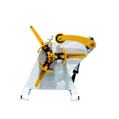
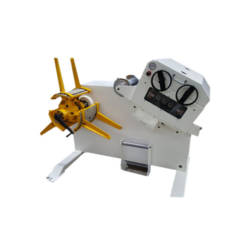
This is the point where the decoiler specification starts to matter to feed accuracy. Mandrel support, brake type and how the brake behaves as the diameter changes are all decisions that get made when the decoiler is chosen, not when the feeder is tuned. Our guide to specifying a decoiler for a coil line covers those choices in order.
Pass Line, Guiding and Lateral Position
Lateral position is the quietest error in the budget, because a strip that enters the rolls at a slight angle still travels the commanded distance. The length is right.
Three things set lateral position, and they are all mechanical. Pass line height decides whether the strip runs level from the straightener exit into the feed nip. Guiding decides whether it stays centred once it is there. And the strip's own camber decides how much correction the guides have to provide in the first place.
The last of those is worth stating plainly, because it is where a lot of setup time is wasted. Camber is a sideways curve that comes from the coil or from slitting.
A guide can hold a cambered strip in position for a while, but it cannot remove the curve, and forcing it with heavy guide pressure simply creates a different problem at the strip edge. If the strip measures straight against a datum and curved once it is free, the correction belongs upstream.
Pass line height also interacts with the straightener. A strip that runs above or below the machine's centre line is being bent as it enters the feed rolls, which changes both the shape and, through the resulting tension, the length. The relationship is set out in how to hit a flatness spec on a coil line.
Pilot Release and the Moment of Truth
Between the feeder and the die there is a hand-over, and it happens in a fraction of a second. The pilot pins in the die enter the holes in the strip to locate it, and at some point the feed rolls let go so the strip can sit where the die put it.
| Release condition | What happens to the strip | How it reads | The cost of getting it wrong |
|---|---|---|---|
| Release too early | The strip is free before the pilots have fully located it | Occasional large errors that look random | Punches get dragged off position. The error is intermittent, which is worse than a consistent one |
| Release too late | The feed rolls are still gripping while the pilots pull the strip home | Short feed that appears on some dies and not others | The strip is stretched between rolls and pilots, which marks the material and loads the pilot pins |
| No release at all | The roll nip holds the strip while the die tries to position it | Progressive length error along the strip | Pilot pin wear, hole elongation and eventually a die crash when a pilot fails |
| Cam timing drifting | The signal arrives at a slightly different point each cycle | Accuracy that is good during a run and poor after a stop | Hard to diagnose because the machine has no fault to report |
| Interface signal latency | The press says release, the feeder acts later | Errors that scale with press speed | Looks like a speed limitation and gets blamed on the feeder |
The setting itself is straightforward to reason about. The feed rolls should hold the strip until the pilots have it, then let go. Everything before that is slip waiting to happen; everything after reduces the time available for the feeder to complete its move.
What makes it hard in practice is that the correct window depends on the die, on the pilot clearance and on how fast the press is running, which is why pilot release timing deserves its own verification step rather than being set once and forgotten.
The press-to-feeder interface matters here for the same reason. Synchronising the motion profile to the press stroke is a separate exercise from setting release timing, and both have to be right before the line will hold tolerance at speed. The interface side is covered in how to synchronise a servo feeder with the press stroke.
Speed, Cycle Time and What Accuracy Costs at 300 SPM
Every line has a speed above which accuracy stops being a property of the machine and becomes a property of the whole system.
| Speed band | What usually limits accuracy first | Typical consequence | Where the fix lives |
|---|---|---|---|
| Up to roughly 150 SPM | Nothing much. The machine's own capability dominates | Accuracy close to the specification | Standard setup and a clean loop |
| 150 to 250 SPM | Slip and loop stability | Length drifts as the coil empties, or tracks the loop | Decoiler brake behaviour and roll surface condition |
| 250 to 400 SPM | Release timing and settling time | Errors that scale with press speed rather than with material | Cam timing, interface latency and the acceleration profile |
| Above 400 SPM on thin strip | Strip dynamics: the material will not settle in the time available | Intermittent misfeeds that no setting removes | Line architecture. It may need a shorter feed, a different strip handling arrangement, or a slower press |
None of those bands is a guarantee; they describe where the constraint usually appears on a well-set line, and the real threshold depends on feed length, material and die design. A short 40 mm feed at 400 SPM is a different problem from a 600 mm feed at the same rate, because the acceleration the strip sees is roughly proportional to the length being moved in the same window.
This is also where scrap behaviour becomes informative. Scrap that rises with speed and falls again the moment the line slows down is a dynamics problem. Scrap that rises steadily through a coil and resets when a new coil is loaded is a tension problem.
They look similar in a reject bin and have nothing in common in cause or cure. The relationship between speed and rejects is examined further in why scrap rises at speed on a servo feeder line.
Long feeds at high speed are the hardest combination, because the strip has to accelerate, travel a long distance and stop in the same cycle window that a short feed uses. If that is the production requirement, it belongs in the line specification rather than in the setup sheet.
How fast a servo feeder can feed and stay accurate sets out how to test that limit on a real machine.
How to Verify Feed Accuracy Before Production
A feed accuracy claim is only meaningful next to the method used to measure it. Three strokes and a pair of calipers will confirm the machine moves; they will not tell you what happens over a full coil at production speed. The verification below is the sequence that actually predicts line behaviour.
| Test | What it measures | Sample size that means something | What it cannot tell you |
|---|---|---|---|
| Static feed length check at low speed | Whether the pulse constant is correct and the mechanics are sound | 10 consecutive feeds at a fixed position | Anything about behaviour at production speed or under tension |
| Feed length against command, at speed | The real repeatability the die will see | At least 50 feeds, recorded, not observed | Whether the error drifts through a coil |
| Full-coil drift test | How much back tension at the tail changes the result | Measurements at the head, middle and tail of one complete coil | Coil-to-coil material variation |
| Slip check with marked strip | Whether the roll is actually moving the strip or merely turning | Two marks per feed over a full coil | Why the slip occurs, only that it does |
| Loop variation recording | Whether length errors track the loop rather than the stroke | Continuous recording across a coil change | The interaction with release timing |
| First-article with the real die | Whether the whole budget holds where it matters | Enough parts to cover a coil change | Whether the result will still hold at full rate |
The full-coil drift test is the one most often skipped and the one that catches the most problems. A line that holds ±0.05 mm for the first half of a coil and wanders to ±0.15 mm at the tail will pass a ten-stroke check every time and still produce rejects on every coil.
Record the numbers rather than watching the machine. Feed accuracy problems are statistical before they are visible, and a written record is what turns 'it seems fine' into evidence. The methods are set out in more detail in how to test servo feeder accuracy before production and how to set feed length accuracy.
Where an Error Budget Stops Helping
The error budget is a good framework, and like every framework it has a boundary. There are conditions where no amount of tuning will move the result, because the largest term in the budget is not something the line can adjust. Recognising them early is what separates a short afternoon of work from three weeks of chasing the wrong thing.
| Symptom on the line | What the error budget suggests | What is actually happening | The right response |
|---|---|---|---|
| Error changes between coils of nominally identical material | Adjust the feeder for the new condition | The material varies: temper, thickness profile or coating weight differ from the certificate | Measure the incoming coil. If the variation is real, the answer is incoming inspection or an incoming specification, not a feeder setting |
| Holes measure correct but parts still fail | Feed length | The strip is positioned correctly lengthwise and wrongly across the width, or the die is worn | Measure lateral position and check die condition before touching the feeder |
| Errors appear only on one die | Line setup | That die has different pilot clearance, a different strip width or a different progression | Treat it as a tooling question. The line is not the variable here |
| Error grows steadily through a shift | Thermal drift in the drive | Often friction and temperature in the roll nip, or lubrication changing as the system warms | Re-verify after a warm-up period, then set the reference. A cold reference is a wrong reference |
| Error appears only on thin-gauge work | Slip | Buckling or pinching, because the strip cannot resist the forces the heavier setup applies | Change the gap and support arrangement rather than increasing pressure. See setting up a servo feeder for thin-gauge strip |
| Occasional double feeds with no pattern | Control fault | Usually a loop or pilot-release interaction, not the drive | Record the loop and release signals together. See preventing double feeding on a servo feeder |
The honest summary is that the error budget tells you where to look, not where to fix. Two of the six conditions above are answered by changing a setting. The rest are answered by changing material control, tooling, warm-up practice or line architecture — decisions that sit well outside the feeder's parameter list.
There is a second limit worth naming, and it applies to the specification itself. A line built to hold ±0.05 mm at 200 SPM will not hold that figure at 450 SPM on the same feed length, not because anything has degraded but because the time available for settling has been halved.
When a supplier quotes a single accuracy number without a speed and a feed length attached, the number is not usable for a decision.
What to Ask For When Specifying a Feed Line
The questions below exist because the answers change the accuracy you will actually get, and because a general-purpose enquiry form will not surface any of them. Ask them in writing and compare the replies, not the covers.
- The accuracy figure together with the speed and feed length it was measured at. A repeatability claim without those two numbers cannot be compared with anything.
- The measured method: what was measured, with what instrument, and over how many feeds.
Static checks and running checks are different claims. - The roll coating offered as standard and as an option, and how it behaves on the surface finish you actually run.
This is the largest single influence on slip. - Minimum and maximum strip thickness, not an average, and the yield strength the maximum thickness figure was calculated at.
- How the drive handles a long feed at speed, and whether the rated throughput applies at the longest feed length you plan to run.
- The pilot release interface: what signal the feeder expects, what latency it introduces, and whether the timing is adjusted in the feeder or in the press.
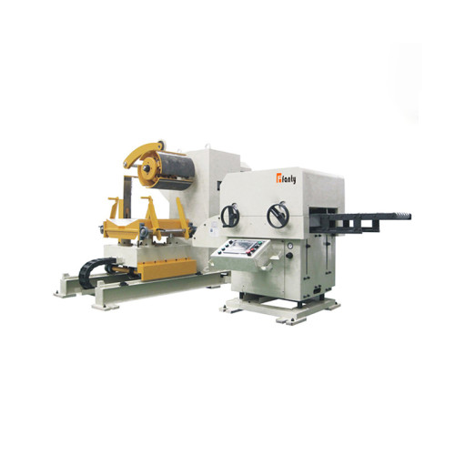
- The decoiler and loop arrangement as a system, not as three separate machines.
Most feed accuracy problems at the tail of a coil are specified in that interface. - What the acceptance test will be, and who supplies the material for it. A machine accepted on the supplier's sample strip and used on yours has not been accepted on the material that matters.
One practical note on how to use the list.
Frequently Asked Questions
What feed accuracy should I specify for a progressive die?
Start from the die, not from the machine. Add up the tolerances that matter downstream: hole-to-hole position, pilot clearance and the allowance the die gives you to begin with.
If the die allows ±0.10 mm, specifying a feeder at ±0.02 mm buys nothing and leaves no budget for the other five error sources. Most progressive stamping work sits comfortably in the ±0.05 to ±0.10 mm band at production speed.
Will a servo feeder hold ±0.05 mm on a real production line?
It can, under conditions worth stating: clean strip with light and controlled oil, a stable loop, a coil whose diameter range the brake is matched to, and a press speed where the strip has time to settle. Remove any of those and the line result will be worse than the machine result, which is why the figure has to be quoted with a speed and a feed length next to it.
How much does back tension change feed length?
Enough to matter at the tail of a coil. On a line that holds ±0.05 mm through the first two thirds of a coil, it is common to see a drift toward ±0.10 to ±0.15 mm in the last few metres, because the rising tension at the reduced diameter is asking the feed rolls to grip harder than they were set for.
A full-coil drift test shows this in an afternoon, and the fix is usually in the decoiler brake rather than the feeder.
At what speed does feed accuracy start to fall away?
There is no universal number, but the pattern is consistent. Up to roughly 150 SPM the machine's own capability dominates. Between 150 and 250 SPM slip and loop stability take over. Above 250 SPM release timing and settling time become the leading terms. Above 400 SPM on thin strip, accuracy becomes a line architecture question rather than a settings question.
Can feed accuracy be improved on a line that is already installed?
Often yes, and usually without changing the feeder. The sequence that gets results is: verify the loop and the decoiler brake across a full coil, check the roll coating against the actual strip surface, confirm the pass line and lateral position, then re-time the pilot release.
In most cases the accuracy problem was in one of those four, and the feeder was doing exactly what it was told. The improvement methods are covered in how to improve feed accuracy on a press line.
What is the single most common cause of length variation?
The loop, in one form or another. Not because loops are complicated, but because they are the interface where two machines that never talk to each other — the decoiler and the feeder — have to cooperate.
A loop that is too tight, too short or controlled by a brake that behaves differently at full coil and empty coil will produce length variation that looks like a feeder fault and is not one.
Where to go next
Feed accuracy is the third of the four coil line clusters. The straightening and decoiler decisions that set up the rest of the budget are covered in their own guides.
Read the 3-in-1 decoiler straightener feeder guide