Is Your NC Servo Feeder Roll Gap Set Too Tight?
Roll gap is the setting operators adjust first and understand least. The instinct is always to close it down — a tighter gap feels like better grip, and better grip feels like better accuracy. On thin or coated material that instinct costs you surface quality, and on heavy material it costs you roll life. An NC Servo Feeder running at ±0.05 mm and 200 SPM has a usable gap window that is narrower than most people expect, and it is defined by the material rather than by the machine.
This guide gives you four signs that the gap is too tight, a setting table by material and thickness, and a five-minute check you can run without stopping production for long. Roll and gap configuration options are listed across the NC Servo Feeder range if you are still specifying.
What Roll Gap Actually Controls
The gap between the upper and lower feed rolls does two jobs at once, and they pull in opposite directions.
Its first job is to generate traction. The rolls need enough normal force on the strip to accelerate it and stop it without slip. Its second job is to let the strip pass without deforming it. Close the gap and you get more of the first and less of the second. There is a sweet spot, and on any given material it is surprisingly narrow — often less than 0.1 mm wide.
The mechanism people miss is what actually transfers force. It is not the gap number itself but the elastic deflection of the roll under load. Rolls are hardened steel, but they are not infinitely stiff. A roll that deflects 0.03 mm under 4 kN of clamping force will let strip through slightly thicker than the static gap setting. That is why the gap that works on a stopped machine is not always the gap that works at 200 SPM.
Four Signs the Gap Is Too Tight
These are the symptoms that point to over-clamping rather than under-clamping. They are easy to confuse with a slip problem, which is why operators often tighten the gap further and make things worse.
- Roll marks on the strip surface. Faint transverse bands that appear at every feed stroke. On pre-painted or galvanised material this is a scrap part, not a cosmetic issue.
- Thickness reduction after the feeder. Micrometer the strip before and after. A measurable reduction means the rolls are cold-working the material, which changes its forming behaviour downstream in the die.
- Coating pickup on the roll face. Zinc, paint or lubricant residue building up in a band across the roll. Once pickup starts it snowballs, because the deposit raises local pressure and attracts more material.
- Growing slip at speed. Counter-intuitive but common. Past a certain clamping force the strip is compressed, its contact patch changes, and the roll starts to skid instead of grip. Accuracy gets worse as the gap gets tighter.
Gap Settings by Material and Thickness
Treat these as starting points. The multiplier is the ratio of gap to nominal strip thickness, and it is the part worth remembering.
| Material | Thickness | Gap multiplier | Starting gap | Watch for |
|---|---|---|---|---|
| Cold-rolled steel (CRS) | 0.8 mm | 1.00–1.02× | 0.80–0.82 mm | Surface marking at high clamp force |
| Cold-rolled steel (CRS) | 2.0 mm | 1.00–1.02× | 2.00–2.04 mm | Roll deflection under load |
| Galvanised steel | 0.9 mm | 1.02–1.05× | 0.92–0.95 mm | Zinc pickup on the roll face |
| Pre-painted steel | 0.6 mm | 1.05–1.08× | 0.63–0.65 mm | Paint damage, immediate scrap |
| Stainless 304 | 1.2 mm | 1.00–1.03× | 1.20–1.24 mm | Work hardening at the roll contact |
| Aluminium 5052 | 1.5 mm | 1.03–1.06× | 1.55–1.59 mm | Soft surface, easy to dent |
| HSLA 340 | 2.5 mm | 0.98–1.00× | 2.45–2.50 mm | Needs force; watch roll life |
The pattern is consistent: the softer or more coated the surface, the wider the gap must be. HSLA is the exception that proves the rule, because it needs high clamping force and can take it — the gap can actually sit slightly under nominal thickness without harming the part.

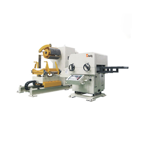
Production assembly in Fanty factory for NC Servo Feeder
A Five-Minute Gap Check at the Machine
Run this before you touch the setting. It stops you from fixing the wrong problem.
- Micrometer three points across the strip width before and after the feeder. A uniform reduction across the width points to the gap setting. A reduction on one side only points to a parallelism problem instead.
- Wipe the roll face with a clean cloth. Grey or white residue means coating pickup. That residue changes the effective gap even if the setting has not moved.
- Run ten strokes at production speed and measure feed length. Note the spread. Then open the gap by 0.04 mm and repeat. If accuracy improves, the gap was too tight.
- Check roll temperature by hand after twenty minutes of running. Rolls that are noticeably hot to the touch are being asked to do too much work.
When the Gap Is Not the Answer
Three problems look like gap problems and are not.
Slip caused by low roll pressure. Gap and pressure are separate settings on most machines. You can have a correctly sized gap and insufficient spring or hydraulic pressure, in which case the rolls do not grip even though the geometry is right. Adjust pressure, leave the gap alone.
Slip caused by contaminated rolls. Oil carried in from the decoiler, or a lubricant that has migrated onto the strip, cuts the coefficient of friction. The rolls are set correctly and simply cannot grip. Clean the rolls and review your lubrication point — lubrication belongs at the die, not at the feeder.
Slip caused by the straightener. A straightener pulling harder than the feed rolls can push creates a tension differential that shows up as apparent slip at the feeder. If the strip is under tension when it reaches the feed rolls, the problem is upstream. FANTY machines are built to hold ±0.05 mm at 200 SPM, and that figure assumes the whole line is set up as a system — gap, pressure, straightener drag and loop control all working together rather than each adjusted in isolation.
Setting Gap and Pressure Together
Gap and pressure interact, and setting them in the wrong order is why so many lines end up over-clamped. The correct sequence is pressure first, gap second, because pressure determines how much the roll deflects and therefore what the effective gap becomes under load.
Start by setting roll pressure to the middle of the manufacturer's range for the material thickness. Run ten strokes and measure feed length spread. If the spread is wider than your tolerance, raise pressure in small increments until it tightens. Only when pressure is settled should you touch the gap, and then only in 0.02 mm steps. Each adjustment should be followed by the same ten-stroke test so you can see the effect rather than assume it.
There is a practical limit to this process. Once pressure is at the top of its range and the gap is at 1.00× thickness, you have exhausted the settings, and further tightening will only damage strip and rolls. At that point the real problem is elsewhere on the line, and continuing to adjust the feeder is a dead end.
- Order matters: pressure, then gap. Reversing the sequence means every gap change also changes the effective pressure.
- Step size: 0.02 mm on the gap, small increments on pressure. Large jumps hide the point where performance peaked.
- Stop condition: when ten consecutive strokes hold the feed length within your part tolerance, stop adjusting. Further tightening trades surface quality for nothing.
- Record it: gap and pressure belong in the setup recipe alongside feed length and speed, so the next run starts from a known point.
Roll Gap Questions From the Press Floor
Should the gap be exactly the strip thickness?
Rarely. Bare cold-rolled steel works well at 1.00–1.02× thickness. Coated material needs 1.03–1.08×. Setting the gap to the exact nominal thickness is a common default that marks galvanised and painted strip.
Can I set the gap with a feeler gauge?
For a static starting point, yes. For production, no. Feeler gauges do not account for roll deflection under load, and that deflection is often the difference between holding tolerance and slipping.
Why does accuracy get worse when I tighten the gap?
Because past a certain point the strip is compressed rather than gripped. The contact patch changes, the effective coefficient of friction drops, and the roll skids. Tighter is not stronger.
How often should the gap setting be verified?
After every coil change on thin or coated material, and at the start of every shift on bare steel. It takes two minutes and prevents the slow drift that nobody notices until scrap rises.
Not Sure Where Your Gap Should Sit?
Send us your material grade, thickness, coating and feed length. We will return a starting gap, a pressure figure and the two measurements that tell you whether it is right.
Request Roll Setup Data