Why Does a Servo Feeder Only Fail at High SPM?
A line that holds ±0.05 mm at 90 SPM and drifts to ±0.30 mm at 190 SPM is not a worn machine. It is a machine whose feed window, inertia and release timing were all sized for the slower speed.
Five causes account for most of these cases, and three test runs separate them before anyone reaches for a screwdriver.
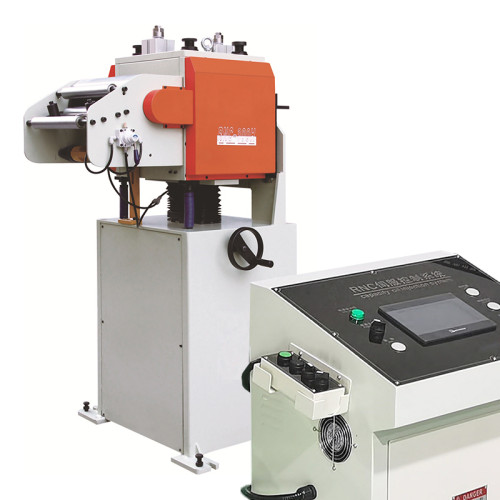
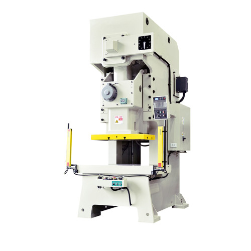
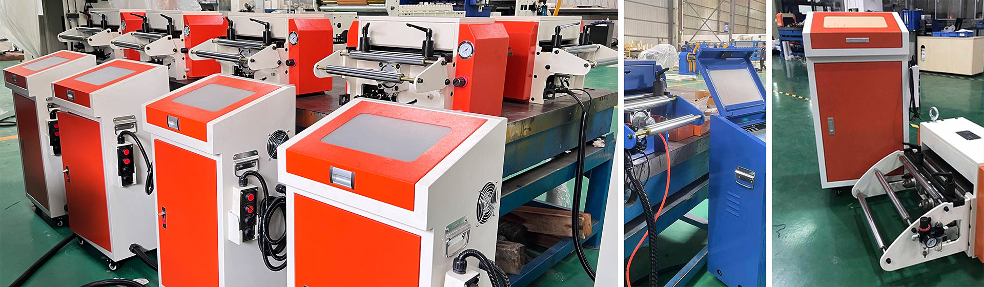
Everything below applies to a standalone NC servo feeder feeding a mechanical or servo press, with the feeder mounted on its own base rather than integrated into a straightening frame.
Separate Speed From Everything Else First
Run the same program at 60, 120 and 180 SPM with the same coil, the same die and the same operator. Measure ten consecutive parts at each speed and plot the spread.
If the spread is flat to 120 SPM and then doubles, the fault is speed-dependent and the list below applies. If the spread is wide at all three speeds, stop reading and look at the die and the material instead.
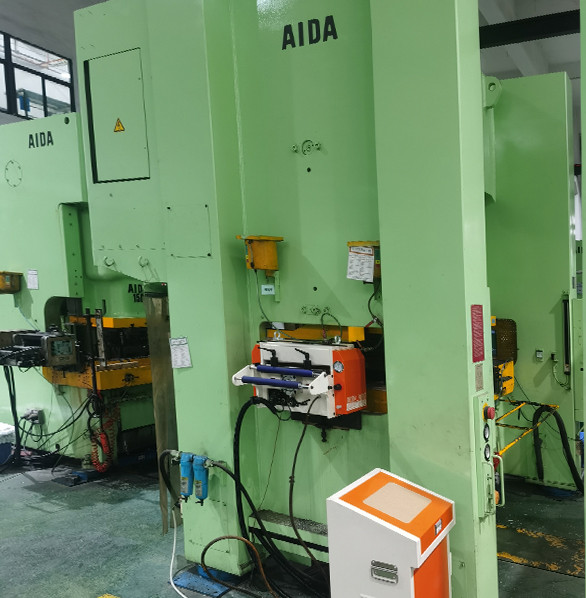
Check the press before the feeder. A press whose slide velocity varies with speed changes the time available for the feed, and that alone can halve the window at the top end.
Log the actual feed length from the controller, not from the part. A part that measures short may have been fed correctly and moved during forming, which is a die problem wearing a feeder costume.
The Feed Window Closes Before the Servo Settles
At 180 SPM the press gives 333 ms per stroke. A 200 mm feed at 1.2 m/s takes 167 ms, and accelerating to that speed and back takes another 90-140 ms.
That leaves almost nothing for settling, and the pilot pins enter while the strip is still ringing. The result is a feed length that reads correct in the controller and a part that is 0.2 mm off.
The window is arithmetic, not opinion: available time minus acceleration, constant-velocity and deceleration time equals settling time. Below 30 ms of settling, most feeders will not hold ±0.05 mm.
Two fixes work. Shorten the feed by running two strokes per part where the die allows it, or raise the acceleration and accept a higher peak torque from the drive.
The third fix is unpopular and usually correct: reduce the speed. A line that runs 160 SPM reliably beats a line that runs 180 SPM and stops twice a shift for a die repair.
Torque headroom is what pays for the first fix. A drive sized at exactly the calculated torque will not deliver the acceleration a short window needs, and the symptom looks identical to a slipping roll.
Ask for the peak torque figure at the speed you run, not the continuous rating. Most feeder datasheets quote continuous torque and leave the peak figure to a footnote.
Following Error Rises With Roll Inertia
A servo drive reports following error in encoder counts, and it grows with the square of speed for a given move profile. Doubling the speed quadruples the torque needed to accelerate the roll mass.
On a feeder with 90 mm rolls and a 5:1 reduction, the reflected inertia is dominated by the rolls themselves. A heavier roll set for wide strip makes the same move profile harder at every speed.
Watch the following error on the drive display during a run at production speed. A peak above 40 counts that settles within 20 ms is normal. A peak that stays high through the dwell is a tuning or inertia problem.
Auto-tuning at 60 SPM and running at 180 SPM is the common mistake. Tune at the speed you produce at, then verify at 20% above it.
Gain that is too high produces overshoot and a visible shudder at the end of the feed. Gain that is too low produces a soft landing and a strip that has not stopped when the pilot pins arrive.
Strip Slips Only at the Top End
Grip is a function of contact pressure, contact area and the oil film between them. All three behave worse at speed.
At 180 SPM the strip passes the rolls in 40-60 ms, and the oil film has no time to squeeze out. A film of 3-5 µm on 0.8 mm cold-rolled steel is enough to drop the effective friction coefficient by a third.
The signature is a feed that is correct on the first stroke after a stop and progressively short over twenty strokes. The controller shows the commanded length, so the drift only appears in the parts.
Increase roll pressure in 0.5 bar steps and watch the part length, not the gauge. Above roughly 4 bar on 0.8 mm stock you start marking the surface, which trades a dimension problem for a cosmetic one.
Roll condition matters more at speed than at low speed. A roll with 0.05 mm of polishing wear holds at 90 SPM and slips at 180, because the contact patch that used to be enough is no longer enough.
At what speed does a feed window typically run out?
Above 160-200 SPM on a 150-250 mm feed, depending on press dwell. Below 30 ms of settling time, ±0.05 mm is not achievable on most machines.
How much following error is normal on a 200 mm feed?
A peak under 40 encoder counts that settles within 20 ms. A peak that persists through the dwell points to tuning or roll inertia, not to the material.
Can 0.8 mm strip slip with 4 bar of roll pressure?
Yes, if the oil film is heavy. Above 4 bar on 0.8 mm cold-rolled you also risk surface marking, so clean the rolls before adding pressure.
Does a 300 SPM rating mean 300 SPM on any feed length?
No. Ratings are quoted at a specific feed length, usually 100 mm, and at a stated duty cycle. Halve the feed and the achievable speed rises; double it and the rating falls.
How long does the three-speed test take?
About 40 minutes, including ten parts at each speed and the measurement. It is faster than any single component swap.
Pilot Release Timing Drifts With Speed
A mechanical pilot release is driven from the press crank, so its timing in degrees is fixed and its timing in milliseconds shrinks as speed rises.
At 90 SPM the release opens 55 ms before the pilots enter. At 200 SPM the same 30° of crank is 25 ms, and the strip is still moving when the pins arrive.
The evidence is on the pilot pins and the pilot holes. Look for a crescent-shaped mark on the leading edge of the hole, which is the pin catching a moving strip.
A servo-driven release set in milliseconds rather than degrees removes the speed dependence, at the cost of a controller axis and a setup parameter that has to be right.
Verify with a strip of paper, not with the drawing. Tape a strip across the die, run one stroke at production speed, and read where the pilot punched through relative to the hole centre.
The 40-Minute Check Sequence
Work down this list in order. Each test rules a cause out or in, and the first one that fails is where the work stops.
| Test | What to read | Verdict if it fails |
|---|---|---|
| Three-speed part spread | Spread flat to 120 SPM, doubling at 180 | Speed-dependent fault, continue |
| Controller vs part length | Commanded 200.00, part 199.80 | Strip slip or die movement |
| Following error trace | Peak counts and settle time | Inertia or tuning, not material |
| Roll witness marks | Polished bands, oil film visible | Grip loss at speed |
| Paper strip pilot test | Punch position against hole centre | Release timing drift |
- Change one variable per run; two changes produce two suspects.
- Measure parts, not the controller display.
- Run the tests on the coil that fails, not on a fresh one.
- Record the ambient temperature; a cold morning changes oil viscosity and grip.
The Rated SPM Figure Assumes Four Things
Nameplate speed is quoted at one feed length, one material and one duty cycle. Change any of the three and the number is fiction.
The common convention is a 100 mm feed, 1.2 mm mild steel, 800 mm width, and a 60% duty cycle. A 250 mm feed at the same rating is a different machine.
Speed also has a cost that the rating hides. Running 15% faster shortens roll life and increases marking on coated stock, and the saving is often smaller than the rework it creates.
And some faults are not speed-dependent at all. A die with 0.02 mm of pilot clearance will misalign at any speed once the strip has 0.1 mm of camber, and no feeder adjustment recovers it.
Once the feeder is behaving, the remaining error usually comes from upstream or downstream of it.
The error budget from decoiler to die, and which part of it each fix actually removes, is set out in the coil line guide library.
Pilot release timing has its own measurement procedure, which is worth reading before changing any release parameter. That sequence is in our coil line knowledge base.
Where to go next
Speed-dependent error is one slice of a larger budget that runs from the coil to the die. If the feeder is already correct, the next number to attack is upstream.
The Coil Line Guide Library