Why Does Strip Drift Through an NC Straightener Feeder?
Three coils in a row ran to the left edge and the die's entry guide wore a step into its left side. The obvious suspect was the guide, so the guide was replaced. Two shifts later the step was back.
Lateral drift is the fault most often blamed on the last component the strip touches. On an NC straightener feeder it usually starts further back, at the coil, the alignment or the roll gap.
This is how the five causes were separated on that job, the measurements that did the separating, and the cases where the head genuinely cannot help.
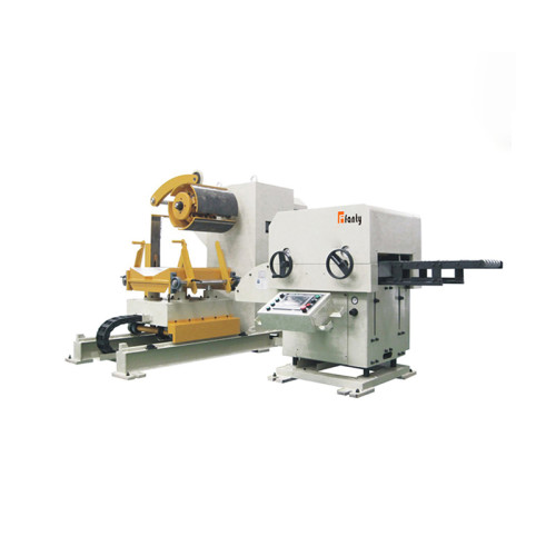
How lateral position fits into the wider error budget is set out in the 3-in-1 decoiler straightener feeder guide. The machine range is listed under our machines.
The Complaint Was Always the Same Edge
The strip walked left, always left, and the operator had learned to compensate by nudging the coil on the mandrel. That compensation hid the trend and made the fault look intermittent.
Three details in the complaint pointed away from the guide. The drift was worse at the tail of a coil than at the head. It was worse on the second shift, after the line had warmed through.
And it changed direction when the coil supplier changed.
A worn guide produces a constant offset. A fault that varies with coil diameter, line temperature and coil source is a fault that lives in geometry or in the material.
The guide was still replaced, because the step in it was real. It just was not the cause, and replacing it cost a shift that would have been better spent measuring.
Five Causes, in the Order Worth Checking
The order matters because the cheap checks come first, and because one of the five can only be confirmed by ruling out the other four.
- Line alignment. If the mandrel axis is not square to the line centre, the strip enters the head at an angle and steers toward the far side. Typically this shows as a drift that grows with the distance between the decoiler and the head.
- Roll skew across the head. If one side of a roll pair is tighter than the other, the strip steers toward the tight side, in the same way a car pulls toward a dragging brake. This cause is easy to miss because the gap looks correct at the centre.
- Entry guide clearance. Guides set too wide let the strip wander before the first roll. Guides set too tight clamp the strip and create a steering effect of their own, while wearing the edge they touch.
- Coil set and crossbow. A coil wound with crossbow presents a strip that is curved across its width at entry. The head removes the curvature, and while it does, the strip has a lateral component to work out.
- Camber from the mill or the slitter. A strip with camber tracks to one side no matter how the line is set. This is the cause that has to be confirmed by measurement, because it cannot be adjusted out.
On the job in question, causes one, two and five were all present.
Alignment accounted for most of the constant offset, roll skew for the speed dependence, and camber for the change of direction when the supplier changed.
The Test That Separates Alignment From Camber
Five checks, run in this order, separate the causes in under an hour on a stopped line.
| Check | What it tells you | Where it misleads |
|---|---|---|
| String line or laser down the line centre, measuring the mandrel axis | Whether the decoiler is square to the head, to within about 0.5 mm over the head length | Reads correctly even when the head itself is off centre, because the reference is the head |
| Camber on a 2 metre sample laid on a floor plate | How much lateral curve arrives from the mill or the slitter, against a typical 5 mm acceptance limit | One sample from one coil describes that coil, not the delivery |
| Roll gap measured at both edges with feeler gauges | Whether the gap differs across the width, above roughly 0.05 mm | A gap difference can be within tolerance cold and open up once the head reaches running temperature |
| Entry guide clearance at each side | Whether the guides are guiding or clamping, against a typical 0.5 to 1.5 mm per side | Worn guide faces read tight at the ends and wide in the middle |
| Strip edge position before and after the head | Whether the drift is created inside the head or arrives with the strip | Only meaningful if the strip is pulled straight at entry, so it must follow the alignment check |
The last check is the one that ends the argument. If the strip is centred before the head and off centre after it, the head is creating the drift.
If it is already off centre before the head, the head is only passing it through.
Warm-up matters on the roll gap check. A head that has run for three hours is not the same machine as a head that has run for five minutes, and a gap that is parallel cold can stop being parallel hot.

Setting the Entry Guide Without Creating the Problem
Entry guides are the most frequently over-adjusted component on the machine, and the correction is usually to open them, not close them.
Guide the strip, do not clamp it. A working clearance of roughly 0.5 to 1.5 mm per side depending on width keeps the strip near the centreline without forcing it.
Clamping the strip turns the guide into a steering device and wears the edge.
Set the guides from the line centreline, not from the strip. Setting each side to the strip edge carries the strip's own position into the setting, so an error at the coil is built into the machine.
Correct the roll gap parallelism before touching the guides. A gap that differs across the width will steer the strip regardless of where the guides sit, and closing the guides to fight it only adds edge wear.
Recheck after warm-up. The final gap and guide check belongs on a head that has reached running temperature, not on a cold machine.
Where the Head Cannot Help
A straightener can correct a great deal of longitudinal shape. Lateral drift is a different problem, and there are cases where the honest answer is that the head is not the right place to solve it.
Camber above the slitting tolerance. Once a strip carries more than roughly 5 mm of camber over 2 metres, no amount of roll setting removes it.
The strip has to be rejected, re-slit or accepted with a guiding system that follows the edge.
A telescoped or edge-damaged coil. If the wraps have stepped out or the edge is torn, the strip arrives already off centre and no head setting recovers it. That is a coil handling and storage issue.
Drift that only appears above a certain speed. When the fault appears suddenly at a particular line speed, the cause is usually tension dynamics or a brake that is losing control, not geometry.
Slowing the line hides it, and adjusting the guides wastes a shift.
Over-rolling one edge. A head set to work harder on one side can flatten one edge more than the other, which bows the strip and moves it laterally. The machine can create this fault as easily as it can remove one.
FANTY has been building coil lines for twelve years, and the pattern in these cases is stable.
Roughly half the lateral drift complaints we are called to end at alignment and roll gap, and about one in ten ends at the coil supplier.

Keeping Strip Centred Across a Coil Change
Most drift is discovered on a Monday after a coil change, which is a hint about where the prevention work belongs.
Check alignment after any foundation work, any relocation and any change to the line layout. A line that has been moved is a line that has to be re-squared.
Keep a record of camber by coil supplier. Over a few months that record tells you which supplier to brief, and it converts a recurring fault into a purchasing conversation.
Log the strip edge position at the start of each coil. A single reading at coil start is enough to catch a drift before it wears a step into the die guide.
Inspect the die entry guide on a schedule. Edge wear of 0.3 mm per shift is not unusual on a drifting line and almost nil on a centred one, so the guide is a useful indicator of how well the line is tracking.
Where the strip is cambered by nature and the part cannot tolerate a re-slit coil, a sensor-guided edge guide that follows the strip is a legitimate answer.
It is a different solution from a straightener, and it is worth saying so rather than tuning the head indefinitely.
Questions that come up once strip drift has been traced.
How much camber can a straightener feeder remove from a 2 metre sample?
Very little. Camber is lateral, not longitudinal. Above roughly 5 mm over 2 metres the coil is outside slitting tolerance and has to be rejected or re-slit.
How much roll gap difference causes drift across a 300 mm strip?
Around 0.05 mm is enough to start steering the strip on thin material, and the effect grows with line speed and with head temperature.
How tight should entry guides be set?
Roughly 0.5 to 1.5 mm per side, depending on strip width. Tight enough to touch the strip is too tight, because the guide then steers rather than centres.
Can strip drift be corrected on the decoiler instead?
Only where the cause is tension asymmetry. Better brake control reduces one cause of drift, but it cannot correct an alignment error or a cambered coil.
Where to go next
Lateral position is one line in the error budget that decides whether parts land where the die expects them. The full budget, from coil to die, is worked through in the feed accuracy guide.
our coil line knowledge base