Which Foundation Does a Heavy Duty Decoiler Need?
The heaviest thing a coil line does to a building is not the machine. It is the coil, plus the moment that coil creates while it hangs off one side of the base.
A heavy duty decoiler is normally specified by coil weight, and the floor is normally checked by machine weight. Those two numbers are not the same load case.
This walks through the loads that actually reach the slab, a worked example on a 10-tonne coil, and the situations where a standard industrial floor is the wrong answer.
Loads That Reach the Slab, and One That Does Not
Three loads arrive at the anchor pads, and one of them is usually missing from the data sheet.
Machine dead weight. A decoiler rated for 10-tonne coils typically weighs 4.5 to 6 tonnes on its own. This is the number every quotation states.
Coil weight. Up to the rated maximum, sitting on the mandrel, offset from the frame centreline. This is the number that changes the load case.
Dynamic allowance. Coil car loading, crane set-down and brake torque all add a multiplier rather than a steady load. A factor of 1.3 to 1.5 on the static sum is the usual planning assumption.
The load that does not reach the slab is the braking torque itself. It goes into the frame and the anchor bolts as shear, not into the floor as bearing pressure.
That distinction matters when you compare a decoiler quotation with a foundation drawing. Shear capacity and bearing capacity are checked separately, and a floor can pass one while failing the other.
Worked Example: A 10-Tonne Coil on a 1,250 mm Mandrel
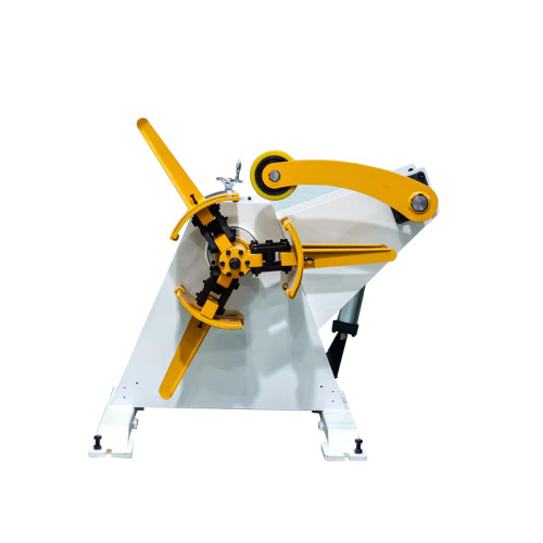
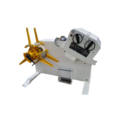
Take a heavy duty decoiler with a 1,250 mm mandrel, rated for a 10-tonne coil on a 508 mm bore, with six anchor pads.
Machine weight is 5.5 tonnes and the maximum coil is 10 tonnes, so the static sum is 15.5 tonnes, or about 152 kN.
Apply a dynamic factor of 1.4 for coil car loading and the design load becomes roughly 213 kN.
Spread across six pads, that is about 35 kN per pad, or 3.6 tonnes sitting on each anchor point.
If each pad is 300 mm square, the bearing area is 0.09 m², which puts the local pressure at about 390 kN/m², or 0.39 N/mm².
That is comfortable for a 200 mm reinforced slab on a compacted sub-base, and marginal for a 100 mm slab laid on fill with no reinforcement.
The arithmetic is not the hard part. The hard part is that the coil is not centred, and that is the next section.
Sizing the Anchor Group
Pad count is a trade between bolt cost and floor pressure, and each option moves the problem somewhere else.
| Anchoring Approach | What It Gives You | Where It Costs You |
|---|---|---|
| Four M24 cast-in bolts on a 200 mm slab | Cheapest option, suits machines up to about 5-tonne coils | Edge distance is tight, and a bolt placed 40 mm out cannot be moved later |
| Six M30 cast-in bolts on a 250 mm slab | Lower pressure per pad and more tolerance for coil eccentricity | More concrete, longer cure before the machine lands, higher civil cost |
| Chemical anchors into an existing slab | No cast-in planning, so it suits a retrofit | Depends entirely on the slab being sound, and pull-out testing is not optional |
| Separate mass foundation with grout bed | Decouples the machine from the building floor and damps brake shock | Adds a civil package, a cure period and a grout record to the schedule |
The second row is where most new installations land once coil weight passes 8 tonnes. The extra two bolts do more for the load case than a thicker slab does.
If the floor already exists and the machine is a retrofit, the third row is the only practical route, and it needs a pull-out test on one anchor before the other twenty are drilled.
The Overturning Moment Nobody Calculates
A coil hanging on a mandrel is a cantilever. The moment it creates is what pulls the rear anchor bolts out of the floor.
On the same machine, a 10-tonne coil with its centre of gravity about 0.8 m from the base edge produces roughly 80 kNm of overturning moment.
With a base about 1.8 m deep, that moment translates into roughly 44 kN of additional tension on the back pair of bolts.
Compare that with the 35 kN of compression the same coil puts on the front pads, and the tension case is the one that governs the anchor design.
This is why a decoiler base is deep relative to its height, and why shortening the base to save floor space is a structural decision rather than a layout preference.
It is also why an uncoiler placed close to a wall or a column needs a check that has nothing to do with the machine itself.
Four Checks the Slab Has to Pass
A slab passes or fails on four separate checks, and a floor that passes three of them is still the wrong floor.
- Local bearing under each pad. Keep the pressure under roughly 1 N/mm² for a standard reinforced slab, and lower if the concrete grade is unknown
- Punching shear around the anchor group. Governed by slab thickness and reinforcement, not by concrete strength
- Bolt pull-out. Governed by embedment depth, edge distance and whether the anchor is cast-in or chemical
- Slab flatness under the base. A base that rocks on a 1 mm hump will not stay level, and an out-of-level machine feeds a coil that walks along the mandrel
Flatness is the check most often skipped and the one most often blamed later. A 0.2 mm per metre tolerance under the base is a reasonable target on a new pour.
Where the pad and the base do not meet cleanly, non-shrink grout is the fix. It is a 30 to 50 mm layer, and it should be in the civil scope, not improvised on installation day.
Site Conditions That Rule Out a Standard Slab
Four site conditions turn this from a bolting exercise into a civil project, and recognising them early is worth more than any calculation.
Slab on fill or made ground. Bearing pressure is fine, settlement is not. A decoiler that settles 3 mm out of level on one corner will feed a coil that drifts.
Upper floors and mezzanines. A 15-tonne static load with a dynamic factor rarely suits a suspended slab. This usually means a steel frame design or a move to ground level.
Adjacent precision equipment. Brake torque and coil car travel both transmit shock. Isolation pads help, but separation is cheaper than isolation.
Coil car rails. The rails carry the coil weight plus the car, and they need their own base. Rails laid on an unreinforced slab will move within a year.
A last case has nothing to do with strength. If the pit depth needed to keep the coil centreline at floor level exceeds what the building allows, the machine moves rather than the foundation.
These are the questions that come up once a plant starts measuring its own floor.
How thick does a slab need to be for a 10-tonne decoiler?
200 to 250 mm of reinforced concrete on a compacted sub-base handles the bearing case. Punching shear and bolt pull-out govern from there, so check the anchor group before the thickness.
Can I bolt a heavy duty decoiler to an existing 150 mm floor?
Sometimes, with chemical anchors and a pull-out test. If the concrete grade is unknown or the slab is under 150 mm, plan a local thickening or a separate foundation instead.
How long does a cast-in anchor foundation delay installation?
Plan 7 days of concrete cure before the machine lands, plus 2 days for grouting and levelling. Chemical anchors into an existing slab remove the cure period but add testing time.
Does a 5-tonne uncoiler need the same foundation as a 10-tonne machine?
No. Halving the coil weight roughly halves the overturning moment, and a four-bolt layout on a 200 mm slab is usually adequate.
What flatness tolerance should the slab meet under the base?
About 0.2 mm per metre. Beyond that, shimming becomes a permanent maintenance item rather than a one-off installation step.
Do I need vibration isolation under a decoiler?
Only when the machine shares a slab with precision equipment. Isolators reduce transmitted shock but add a spring element that has to be checked for level drift.
Measuring the Floor Before the Machine Lands
Half a day with a level and a tape removes most of the risk from the installation week.
Existing slab thickness and reinforcement. If there are no drawings, a small core sample answers it in an hour and costs far less than a failed anchor.
Concrete grade or an estimate of it. A rebound hammer reading is not a design value, but it separates a real slab from a screed.
Flatness across the footprint. Survey the whole base area, not just the four corners. The high point is what the machine will sit on.
Clearance for the coil outside diameter. A 1,250 mm mandrel with a 1,500 mm coil needs the space and the crane access, and neither is a foundation question until it is.
Anchor positions against the drawing. Mark them on the floor before drilling, and check the edge distances against the base plate the machine actually arrives with.
Photograph the marked layout. When the machine arrives three weeks later, the photograph is the only record that survives a shift change.
Records That Belong in the Handover File
Foundation work disappears under the machine within hours, so the record has to be made while it is still visible.
Anchor layout as built. Marked-up positions, bolt type, embedment depth and the torque applied to each one.
Grout record. Product used, layer thickness and cure time before loading.
Level survey. Readings across the base after the machine is set, taken before and after the first loaded coil.
Pull-out test result for any chemical anchor installation, on at least one anchor per layout.
Those four sheets are what a service engineer asks for first when a decoiler starts creeping or a bolt shows a witness mark.
| Record | What It Settles Later | Where It Costs You |
|---|---|---|
| Anchor layout as built | Which bolt failed if a witness mark appears | Half a day marking up a drawing after the machine is already in place |
| Grout product and layer thickness | Whether a level drift is a grout problem or a slab problem | A product name nobody remembers by year three unless it was written down |
| Level survey before and after the first coil | Whether the machine settled or was set wrong | An hour of surveying that has to happen before production starts |
| Pull-out test result | Whether a chemical anchor can be trusted under tension | One anchor sacrificed to the test, plus the site or lab time |
The same logic runs through the rest of the machine.
FANTY has supplied coil handling equipment into more than 60 countries, and the installations that stay level are the ones that documented the floor before the machine arrived.


Where to go next
This article sits in the coil handling cluster, one layer below the specification overview. If the foundation question is settled and you are still choosing capacity, type and mandrel, start there.
The Coil Line Guide Library