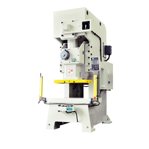
What Happens When an NC Straightener Feeder Misfeeds?
A misfeed on an NC straightener feeder line ends in one of two ways. The press stops with the die intact, or the die takes the hit.
What separates the two outcomes is not the size of the misfeed. It is how much of the strip position the control actually knew about before the ram came down.
This is the sequence from a real crash on a 200 SPM line, and the three gates that decide whether the tool survives.
Sixty Milliseconds Between a Misfeed and a Crash
At 200 strokes per minute the press completes a cycle in 300 milliseconds. The strip is stationary for roughly 100 of those milliseconds.
A servo drive needs about 60 milliseconds to report a position error large enough to matter, and the ram is already committed by then.
That arithmetic is the reason a feed fault and a die crash are not the same event. The control has a window, and the window is short.
What the control does with that window depends on three things: whether the fault is detected at all, whether the detection is wired to the press stop, and whether the ram has already passed top dead centre.
Feed accuracy and die protection are two different systems. One holds the strip in position. The other decides whether to let the press run at all.
What the Line Logged on the Morning It Happened
The case came from a plant running 1.5 mm SPHC, 1,100 mm wide, through an eight-station progressive die on a 200 SPM press.
Job had been running for four hours. The operator had changed nothing since the start of the shift.
The strip carried a heavier oil film than usual because a new coil had been opened with the mill's protective coating still wet.
At 09:41 the feed rolls slipped on the oil film. The strip stopped 4 mm short of the pilot position.
Station two carries the pilot pins. The ram came down with the strip out of position, the pilot hit the strip edge instead of the pilot hole, and the die took the load.
Result: one broken pilot pin, a cracked insert in station three, and six hours of downtime. Scrap was 22 metres of strip and about 400 parts.
The feeder reported no fault. Its position loop closed correctly. The strip simply was not where the feed roll thought it was, and the control had no way to know.

Three Gates Between a Misfeed and a Damaged Die
Every line has three chances to stop before the ram reaches the die. This is how they performed on that job.
| Gate | What It Would Have Caught | Where It Costs You |
|---|---|---|
| Feed roll grip and surface condition | The slip itself, before any position error appeared | Tighter roll pressure marks soft or coated strip on every part |
| Strip position sensor at the die entry | The 4 mm error, before the ram committed | A sensor head in the die area, and a bracket that has to survive the strip |
| Pilot pin load or die protection interlock | An abnormal load on the pilot before the insert cracked | Slower cycles on short feeds where normal load spikes look like faults |
Look at the third row. Die protection systems that monitor load are effective and they are not free.
They need a threshold, and a threshold that is tight enough to catch a pilot pin will also trip on a normal slug build-up.
The second row is the cheapest of the three on most lines, and the one plants add last. A single sensor looking at strip position at the die entry would have stopped this press with the die intact.
The first row was the actual root cause. A roll that grips properly does not slip on an oil film, and grip is a maintenance and setup question rather than a control question.
Those three gates are only part of the story.
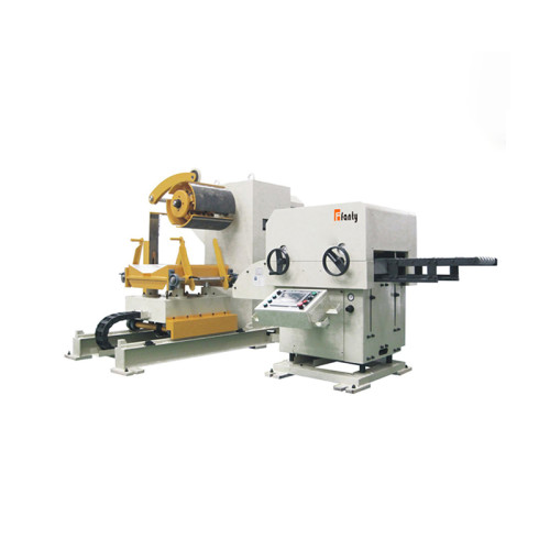
Strip position at the die is the last millimetre of an error budget that starts at the decoiler, and the whole chain is set out in 3-in-1 decoiler straightener feeder guidance.
These are the questions that come back whenever a plant reviews a misfeed that reached the die.
How much slip does it take to bend an 8 mm pilot pin?
On a 1.5 mm SPHC job with 8 mm pilot pins, about 3 mm of short feed is enough to put the pilot on the strip edge instead of the hole.
How fast can a servo drive report a position error at 200 SPM?
Typically 40 to 60 milliseconds from the fault to the stop signal. At 200 SPM that is a fifth of the cycle, and the ram is already moving.
Does a strip position sensor pay for itself after one 6-hour crash?
Usually. Six hours of downtime plus a cracked insert and a bent pilot typically exceeds the cost of the sensor and its bracket by a wide margin.
Should roll pressure be increased to stop slipping on oily strip?
Only up to a point. Past about 3 bar on coated strip the rolls start to mark, and the marks show up as rejects rather than as scrap.
How often should feed roll grip be checked, every 500 hours?
Every 500 running hours, and after every coil that arrives with a heavy oil film. The check takes ten minutes with a spring gauge.
Where Die Protection Stops Working
Die protection is the reason most misfeeds are uneventful, and it has four blind spots worth knowing about.
Slug build-up in a scrap chute. A load monitor watching the pilot sees a normal cycle right up to the stroke where the chute finally blocks and the die takes the hit.
Gradual drift. A feed length that creeps 0.05 mm per hour is inside every threshold until the day it is not. Nothing trips, and the parts are out of tolerance for a shift before anyone notices.
Very short feeds. Under about 8 mm the strip position signal changes so little per stroke that a sensor tuned for a 40 mm feed will not see the error at all.
Thin, springy strip. A 0.5 mm strip can bow in the guide rather than slip in the rolls, and the position sensor at the die entry reads correctly while the strip at the pilot is short.
None of that argues against die protection. It argues for treating it as the last gate rather than the only one, and for fixing the grip problem that caused the slip in the first place.
The line in this case study ran for another three years without a die crash. What changed was the roll grip check, not the control.
How to Set the Release Window on a 200 SPM Line
Pilot release timing is the single most effective setting against a misfeed crash, and it is the one most often left at the factory default.
The pilot pins must enter the strip after the feed rolls have released it, and the strip must be fully stationary before they do.
At 200 SPM, set the release point so the rolls let go no later than 25 milliseconds before pilot entry. Any later and the strip is still moving when the pilot touches it.
Set the pilot entry point so the pins are fully seated at least 15 milliseconds before the ram reaches the working stroke. That margin is what absorbs a small feed error.
Test it with a dial indicator, not by ear. Put the indicator against the strip at the die entry and run 200 strokes. Any movement after pilot entry is a release timing error.
Record the release setting on the job card for every die. Rebuilding the window from scratch at each changeover is how a crash comes back.
Then repeat the test on a wet coil. Oil changes the grip and the release behaves differently, and the wet test is the one that matters.
Feed length accuracy on these machines is held at ±0.05 mm at 200 SPM, and that figure assumes the release window is set correctly. The accuracy does not protect the die on its own.
What to Change After the Crash
Four changes went onto this line after the event, and only one of them cost real money.
- A roll grip check every 500 hours, recorded on the same sheet as the feed length verification
- A wipe on the entry side of the rolls for coils that arrive with a heavy protective oil film
- Strip position sensing at the die entry, wired into the press stop circuit
- A release timing re-check written into the job setup sheet, so it is verified on every die change
The third item is the only capital purchase. The other three are procedures, and procedures are what actually stopped the next crash.
Write the grip check result beside the feed length reading on the same sheet. Two numbers on one line tell the next shift far more than either one alone.
Write the release window onto the setup sheet as a number in milliseconds. A setting that lives in an operator's memory leaves with the operator.
FANTY has been building these lines for twelve years across more than 60 countries, and the crashes we are called out to investigate almost always trace back to a grip or release setting rather than to the machine.
Where to go next
Feed accuracy, pilot release timing and die protection form one cluster in our coil line knowledge base. This article sits under it, one layer below the error budget overview.
The Coil Line Guide Library