What Changes When a Coil Line Feeds a Deep-Draw Press?
An appliance plant moved a stainless sink bowl from pre-cut blanks to coil last spring, expecting a 6 percent material saving and a shorter route to the press.
Material cost fell 5.4 percent. Draw cracks rose from 1.8 to 6.5 percent in the first week, and the toolroom spent eleven days on a die that had run clean for four years.
The die was not the problem. Three things changed the moment the blank started coming out of a strip instead of a stack of cut squares.
A deep-draw press asks the coil line for things a blanking or progressive job never asks: a flat blank, an unmarked surface and a blank position that holds to a fraction of the wall thickness.
What follows is the eleven days, the measurements that ended the argument, and the setting sheet that held afterwards.
Why Pre-Cut Blanks Ran Better Than Coil
The job: 1.0 mm SUS304, a 430 mm round blank, a 250-tonne hydraulic press drawing a 210 mm deep bowl at 18 strokes a minute.
On blanks, the operator loaded a stack, the die located each blank on a ring, and the draw ran at 1.8 percent crack rate for four years.
On coil, the first station cuts the blank and the second draws it. The blank is now located by the strip, and the strip carries everything the coil mill left in it.
Three variables entered the die that day: 2.8 mm per metre of camber, a visible mark band from the straightener rolls, and a lubricant film that the feed rolls had squeezed thinner on one side.
Each one is small on its own. Together they moved the blank far enough to thin one wall of the bowl by 12 percent, which is where the cracks appeared.
What the Blank Station Changes About Feeding
A draw die fed from coil runs in blank mode, which is a different feeding problem from a progressive die.
The feed pitch equals the blank pitch plus the web, so a 430 mm blank in a 450 mm strip advances 442 mm per stroke with a 4 mm web on each side.
That leaves a skeleton of roughly 3.6 percent of the strip, which is the material saving the plant was chasing in the first place.
The tolerance that matters is not feed length. It is lateral position, because the blank's offset from the die centre becomes wall thickness on one side and clearance on the other.
On a 1.0 mm wall, a 0.4 mm blank offset thins one side by about 0.12 mm. A 12 percent wall reduction at a draw ratio near 2.0 is enough to crack SUS304.
Feed length still has to hold, because the blank must clear the cut station before the draw starts. A 0.3 mm short feed leaves a sliver that marks the next blank.
Where Camber Turns Into Wall Thickness
Camber is a lateral bow measured along the strip length, and a draw die is far less forgiving of it than a blanking die.
At 2.8 mm per metre, a 442 mm pitch shifts the strip 1.24 mm sideways on every stroke. The edge guide has to push it back before the cut.
A fixed roller guide pushes back by force, which puts the strip edge under compression. On 1.0 mm stainless that shows as edge wave within 300 strokes.
A servo edge guide follows the strip instead, at 0.1 to 0.3 mm of correction per stroke, and holds the blank within 0.15 mm of centre.
The plant had a fixed guide. The strip buckled against it, the blank shifted inward on the buckle side, and the draw cracked on the opposite wall.
Measured on the finished part: 0.31 mm of wall difference between the two sides of the bowl, which matches the 0.35 mm blank offset recorded at the cut station.

Marks That Only Appear After the Draw
A mark that would be invisible on a flat blank becomes a stretched band once the metal flows over the draw radius.
The rule the plant adopted: any mark you can feel with a fingernail on the strip will be visible on the drawn wall.
Roll marks are the usual source, but the feed rolls, the edge guide and the slitter all leave their own signature, and each one looks different after drawing.
| What the line does | How it shows after the draw | Where it hurts the draw |
|---|---|---|
| Straightener roll mark band | Parallel band across the bowl wall, widened by stretching | Polish and re-chrome the roll set, or accept a cosmetic reject rate |
| Feed roll squeezing the lubricant | Dry patch that scuffs and picks up galling on the punch radius | Die polishing every 8,000 strokes instead of every 30,000 |
| Slitter burr on the coil edge | Edge crack that opens during the draw, always on the same side | Edge trim station or a coil specification with a rolled edge |
| Crossbow in the coil | Wrinkle at the blank holder, worse at the strip centre | Higher blank holder force, which raises thinning elsewhere |
| Guide scrape on the strip edge | Score line that becomes a fold under the blank holder | Guide roller change and a wider strip allowance |
Only the first two were present here. The band ran across every bowl at the same height, which is what pointed the toolroom at the straightener rather than at the die.
Speed, Dwell and the Loop Behind the Press
A hydraulic draw press does not run like a mechanical press, and the coil line has to absorb the difference.
At 18 strokes a minute the average strip speed is 8 m per minute. During the feed window it is closer to 26 m per minute, because the feed happens in 0.9 seconds of a 3.3 second cycle.
That stop-start rhythm is what the loop is for, and a loop that is too shallow turns it into a decoiler problem.
- Loop depth. Size it for at least two feed strokes, so 1.0 m on this job, and check it at the lowest speed the press will ever run.
- Decoiler starts. A shallow loop starts and stops the decoiler 18 times a minute, which heats the brake and shortens its life.
- Loop sensor position. Mount it where the strip cannot slap it on the fast stroke, or the line will trip on a false low-loop signal.
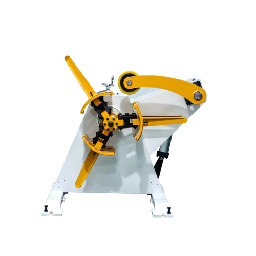
- Accumulator, if fitted. A 3 m accumulator lets the decoiler run continuously at 8 m per minute instead of pulsing at 26.
What a Coil Line Cannot Fix in a Draw Die
It is worth being blunt about the boundary, because suppliers who promise a draw fix with a straightener are selling the wrong machine.
Die clearance and radii. If the punch radius is too tight for the material, no amount of blank flatness will stop the crack. That is a die decision.
Blank holder force. Wrinkles that survive a correct blank still come from the cushion, not from the strip.
Mill residual stress. Coil that was rolled with uneven tension keeps that memory. A straightener redistributes it, it does not delete it.
Draw ratio. Beyond roughly 2.2 on 1.0 mm SUS304, the limiting factor is material elongation, and a flatter blank buys nothing.
Flatness data. A blank that measures 0.05 mm flat on a surface plate can still draw badly, because flatness says nothing about the stress pattern inside the sheet.
What the line can do is remove the three variables it introduced. That is a smaller claim, and it is the one that held.
The Setting Sheet That Held
Five changes took the crack rate from 6.5 percent back to 2.1 percent over three weeks, and it has stayed there for eight months.
- Servo edge guide. Replaced the fixed roller guide and set correction to 0.2 mm per stroke, which holds the blank within 0.15 mm of centre.
- Penetration reduced by 0.15 mm. Less roll bite removed the mark band without losing flatness, because the strip was already close to yield.
- Polished rolls on the draw side. Ra 0.4 instead of Ra 1.6, and the roll set is now checked with a fingernail test at every coil change.
- Lubricant applied at the die only. Pre-lubricated coil was replaced with dry strip, so the feed rolls can no longer squeeze the film unevenly.
- Camber limit on incoming coil. 1.5 mm per metre, measured at goods-in on a 1 m straight edge, with a reject sheet the mill now sees.
The remaining 2.1 percent is the die's own limit at this draw ratio, and the plant has stopped chasing it on the line.
Every line we ship is CE-marked before it leaves the works, and this pattern is consistent across draw jobs: the draw finds the strip defect that blanking hid.
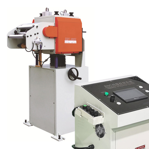
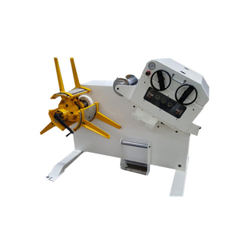
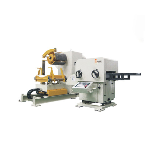
The coil line range we build for draw work uses the same blank-mode logic, with the edge guide specified separately from the feed unit.
Does a 430 mm blank need a 450 mm strip width?
Yes, for a 4 mm web each side plus edge trim. Anything under 8 mm of total web leaves the slitter burr inside the blank and cracks appear on that edge.
How much camber moves wall thickness by 0.1 mm on a 1.0 mm wall?
About 0.35 mm of blank offset, which on a 442 mm pitch means roughly 0.8 mm per metre of camber if the guide corrects nothing at all.
At what draw ratio does a coil-fed blank stop being the constraint?
Around 2.2 for 1.0 mm SUS304. Past that the material's elongation limits the draw and blank position stops being the deciding variable.
How many strokes a minute does a 250-tonne hydraulic draw press allow?
Typically 15 to 22 with a 0.8 second dwell. Plan the loop and the decoiler for the 26 m per minute feed window, not for the average of 8.
Can a straightener remove crossbow from a 1.0 mm stainless coil?
Most of it. A 6-high set with correct penetration takes 0.8 mm of crossbow down to about 0.1 mm, and the rest goes into the blank holder.
Where to go next
This case sits in the stamping solutions cluster, where a line is judged by the process it feeds rather than by its own specification sheet.
The feed accuracy pillar takes the same argument further and splits the error budget from decoiler to die, including the blank position term used above.
Read the feed accuracy error budget