Is Your Decoiler Payoff Speed Matched to the Press?
Two identical lines, same press, same tooling. One runs at 60 strokes a minute and the other stalls every time the coil drops below half.
The difference is rarely the press. It is whether the payoff side was sized on average demand or on real demand.
This article works through the arithmetic behind a decoiler, shows where the coil diameter changes the answer, and names the cases where the numbers on a nameplate will mislead you.

A press does not consume strip steadily. It pulls nothing for most of the cycle, then takes a full pitch in a fraction of a second.
Everything on the payoff side exists to bridge that gap, and the size of the gap is a number you can calculate before you buy anything.
What the Press Asks For, Burst by Burst
Two different speeds live on the same line, and confusing them is the root of most sizing errors.
Average demand is pitch multiplied by strokes per minute. A 300 mm pitch at 60 SPM averages 18 m/min, which sounds modest.
Peak demand is a different figure. If the feed window occupies 0.35 s of a one-second cycle, the strip moves at roughly 51 m/min while it is moving.
A machine sized on the average number will be short by a factor of three during every stroke, and no amount of loop tuning hides that.
So the first question is not how fast the line runs. It is how much of each cycle the strip is actually moving.
| Stroke Rate | Average Demand at 300 mm Pitch | Peak Demand in a 0.35 s Window | Where It Costs You |
|---|---|---|---|
| 40 SPM | 12 m/min | 34 m/min | Peak is already nearly three times the average, even on a slow line |
| 60 SPM | 18 m/min | 51 m/min | A drive sized on the average number falls behind on every single stroke |
| 90 SPM | 27 m/min | 77 m/min | Above 70 m/min the loop pit becomes a building decision rather than a machine option |
Sizing Starts With Three Figures
Three measurements settle the whole calculation. All three are available before a machine is chosen.
- Strip demand per stroke. Feed pitch in millimetres, including any scrap allowance between parts.
- Feed window in seconds. How long the strip is actually in motion inside one press cycle.
- Loop capacity in metres. The length of strip held in the pit or accumulator between the coil and the press.
With those three figures you can state the payoff requirement in plain language, and a supplier can size a drive against it rather than against a rule of thumb.
The loop figure is the one buyers most often leave out, and it is the number that decides how forgiving the line is at high stroke rates.
Worked Example: 300 mm Pitch at 60 SPM
Take a 1.2 mm SPCC strip, 1,250 mm wide, 300 mm pitch, 60 strokes per minute, feed window 0.35 s, loop 8 m.
| Step | Number | What It Means for the Payoff Side |
|---|---|---|
| Average strip demand | 18 m/min | What the coil must deliver over a minute of running |
| Peak strip demand | 51 m/min | What the loop has to absorb during each feed window |
| Loop buffer time | 27 s | How long the press can keep running if the coil stops paying off |
| Mandrel speed at 1,500 mm coil | 3.8 rpm | Low speed, high torque, most of it needed to hold tension |
| Mandrel speed at 600 mm coil | 9.5 rpm | Same strip speed, two and a half times the rotation |
The last two rows explain why a single fixed-speed motor rarely suits a coil line. The strip speed is constant; the shaft speed is not.
A 27-second buffer sounds generous until you watch what happens at a coil change, where the stop lasts longer than that.
Five questions came up in the same meeting as this calculation. Here they are, in the order they were asked.
How many seconds of loop buffer does a 60 SPM line need?
Aim for 20 to 30 seconds at average strip speed. Below 15 seconds the line becomes sensitive to every coil change and every tension hiccup.
Can a 3 kW motor drive a 10 t coil at 18 m/min?
Usually not. Coil inertia and back tension on a 10 t coil demand far more starting torque than the steady-state figure suggests. Check the acceleration case, not the running case.
At what coil diameter does the payoff speed become a problem?
Below roughly 600 mm outside diameter the shaft speed roughly doubles, and a constant-speed drive starts fighting the loop control.
Does the mandrel need to be driven, or will a brake do?
Below 0.5 mm strip a brake is often enough. Above 1.5 mm, and above 30 m/min, a driven mandrel with tension control is the safer specification.
How much strip tension should the coil carry?
Typically 2 to 5 percent of yield strength. On 1.2 mm SPCC that is a light pull, and it is what keeps the strip flat into the loop.
Why the Coil Diameter Changes the Answer
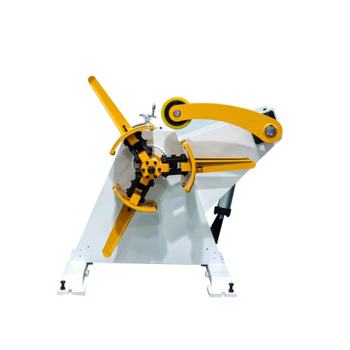
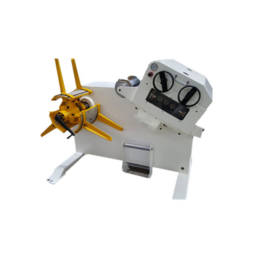
Strip speed is the controlled variable. Shaft speed and torque are both functions of the coil radius, and that radius falls by more than half over one coil.
At 1,500 mm outside diameter a 10 t coil carries an inertia of roughly 2,800 kg·m². Bringing that up to 3.8 rpm in three seconds takes a few hundred newton-metres before any strip tension is applied.
At 600 mm the same coil is lighter and turns faster, so the acceleration torque falls while the running speed rises. The drive has to cover both ends of that range.
This is why a variable-speed drive with tension feedback is the normal specification above about 1.5 mm, and why a fixed-speed motor plus a slip clutch only works on light, slow lines.
The uncoiler end of the same problem is where alignment errors show up, and those are covered in our coil line knowledge base.
Four Assumptions Behind the Formula
The calculation above is honest, but four assumptions inside it are not always true in a working shop.
Constant strip speed. The formula assumes the line runs at a fixed rate. In practice the press ramps up and down, and every ramp is an acceleration case the drive has to survive.
Nameplate coil geometry. A 10 t rating assumes a stated inside and outside diameter. A smaller bore or a tighter coil changes the inertia and the grip.
Clean strip. Back tension is calculated on a flat strip. Camber or a bent edge drags in the guides and adds load the arithmetic never sees.
The empty coil. Near the end, the mandrel alone is turning at 9.5 rpm with almost no inertia to stabilise it, and that is where loop instability usually starts.
None of this makes the calculation wrong. It means the drive should be specified with margin rather than at the computed figure.
What to Specify When the Numbers Do Not Fit
If the calculated demand sits above what a standard machine offers, you have three levers. Each one costs something different.
| Lever | What It Gives the Run | Where It Costs You |
|---|---|---|
| Longer loop or pit | More buffer seconds, so the payoff has time to catch up | Floor space and a pit that has to be built before the machine arrives |
| Driven mandrel with tension control | Payoff speed follows demand across the full coil diameter range | Higher machine cost, plus a drive and encoder to maintain |
| Larger coil and fewer changes | Fewer interruptions, so the loop has less to recover from | Heavier machine, larger coil car, and a crane rated for the load |
| Lower stroke rate | Everything fits inside the existing machine | You pay for the shortfall in output rather than in capital |
The fourth row is the honest option that suppliers rarely put on paper, and it is sometimes the correct answer for a line that only peaks for two hours a day.
Whichever lever you pull, ask for the demand figure in writing so the machine can be checked against it later.
What to Measure on the First Coil
Commissioning is where the calculation meets the strip, and three readings settle the argument.
- Strip speed at coil start and coil end. If the two figures differ by more than a few percent, the drive is not tracking.
- Loop depth at maximum stroke rate. Watch it for a full coil, not for a minute.
- Recovery time after a coil change. From restart to full stroke rate, measured on the clock.
- Mandrel grip after ten coils. A coil that has crept on the mandrel will also have changed the payoff tension.
Write all four into the acceptance sheet. A payoff problem found in the first week costs a parameter change; found in the sixth month it costs a drive.
The specification chain behind these decisions, from capacity to control, is set out in the coil line guide library.
If you are comparing drive options for a specific coil weight, the coil handling product range lists standard mandrel sizes and drive configurations.
Where to go next
This article sits in the decoiler branch of the coil line guide library. It works one calculation through to an acceptance test rather than covering the full specification chain.
Read the decoiler specification guide