How to Load a Coil Without Damaging the Mandrel
Most mandrel damage happens before the coil is on the shaft, in the ninety seconds between the crane hook and the first turn.
A 5 t coil of 1,250 by 2 mm strip, 508 mm bore, was loaded three times a day on a wedge-type decoiler. Two years in, the mandrel was scoring bores and the segments had cracked at the root.
The fix was a loading sequence written on a laminated sheet. Nothing on the machine changed, and the scoring stopped within a month.
The Sequence, and Why Order Matters
The order is bore, sling, height, entry, expansion, first wrap. Skip one and the next step loads the mandrel in a way it was not designed for.
Each step is cheap on its own. A bore check takes two minutes, a height check takes one, and the expansion gauge is already on the valve block.
What makes the order matter is that the failures compound. A coil entered 15 mm low bends the shaft slightly, and a bent shaft then loads every later coil off-centre.
That is how a mandrel that should last ten years reaches the end of its life in two, without a single obvious event to blame.
Check the Bore Before the Hook Moves
The bore is the only surface that touches the mandrel, and it is the one nobody inspects.
Measure the bore at two diameters, 90 degrees apart, at both ends of the coil. A 508 mm bore that reads 512 mm one way and 506 mm the other is 6 mm out of round.
Three millimetres of ovality is the working limit for a four-segment wedge mandrel. Beyond that the segments contact on two lines instead of an arc, and the contact pressure triples.
Burrs on the bore come from the slitter and from strapping that was cut with a knife against the coil face. A 0.5 mm burr is enough to raise a ridge along the mandrel segment.
Rust is the quiet one. A coil stored at a port for three months can carry a 20 to 40 mm band of scale inside the bore, and that band acts like grinding paste.
Clean the bore with a wire brush on a pole before the coil is lifted, not after it is hanging over the mandrel.
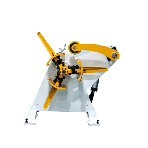
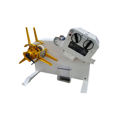
Nothing in this sequence changes on a plain uncoiler. A manual decoiler machine with screw expansion follows the same order, with a torque wrench in place of the pressure gauge.
Sling, C-Hook or Coil Car: What Each Does to the Mandrel
All three lift the coil. They differ in what they do to the bore when the load swings.
A two-leg sling through the bore is the cheapest method and the least controlled. At an included angle of 60 degrees each leg carries 2.9 t on a 5 t coil, and at 30 degrees each leg carries the full 5 t.
Keep the included angle at 60 degrees or less, and use soft slings rather than chain, because a chain edge on a 2 mm strip face will crush the outer wrap.
A C-hook supports the bore over its full length and keeps the coil square to the mandrel. It needs a capacity of 1.2 times the coil weight and a level lift, and it takes two people to land accurately.
A coil car is the only method that removes the swing entirely. The coil sits in a cradle, the car raises it to the mandrel centreline, and the entry is a straight horizontal move.
Above 8 t, or above two coil changes an hour, the car stops being a convenience and becomes the method that protects the machine.
| Check | What to measure | Pass condition | What a fail costs |
|---|---|---|---|
| Bore ovality | Two diameters 90 degrees apart, both ends | Within 3 mm of nominal | Segment scoring, 4,000 to 7,000 USD to re-machine |
| Bore burr and scale | Visual and hand check along the bore | No ridge above 0.5 mm | Ridges on segments, strip marks for months |
| Lift height | Mandrel centre against bore centre | Within 3 mm | Bent shaft, then every later coil loads off-centre |
| Expansion pressure | Gauge on the valve block, held 10 min | 60 to 90 bar, drop under 5 bar | Coil slip under tension, edge damage on the first wrap |
| Segment contact | Witness marks along the bore length | Over 70 percent of bore length | Point loading, cracked segment at the root |
Height, Alignment and the 3 mm Rule
The mandrel is a cantilever. Every millimetre the coil sits off centre becomes a bending moment on the shaft, and the shaft does not forget.
A 5 t coil 20 mm above the centreline applies about 980 Nm to the mandrel root. That is small against the design rating and large against fatigue over 2,000 loadings.
Three millimetres is the practical target, and it is achievable with a fixed-height car or a marked sling length.
Alignment in the other axis matters as much. A coil entered 10 mm out of square drags the segments sideways and wears the wedge faces, which is a 3,000 USD repair on a four-segment mandrel.
Paint a vertical line on the floor at the coil face position and a second one at the far edge. Two lines are enough to land a coil square without measuring anything.

Entering the Mandrel Without a Shock Load
The coil should be drawn onto the mandrel, never pushed onto it by the crane.
Two people on a tag line can hold a 5 t coil steady, and a third controls the crane at creep speed. Entry speed under 0.2 m/s keeps the swing under control.
If the coil stops moving, stop pulling. A coil that jams on a burr and is then forced will drive the burr into the segment face and leave a groove that marks strip for the life of the roll.
Rotate the mandrel slowly by hand or in jog mode while entering. Rotation lets the segments find the bore instead of fighting it.
Never leave a coil hanging on the hook while the mandrel expands. The expansion lifts the coil a few millimetres, and the hook then holds it against the segments instead of the bore.
Expanding, Seating and the First Wrap
Expansion is hydraulic on most machines and mechanical on the smaller ones. Both need a pressure figure, and neither works without a gauge.
For a 5 t coil on a 508 mm mandrel, 60 to 90 bar seats the segments. Hold the pressure for ten minutes and watch the gauge, because a drop of more than 5 bar means a leaking seal or a cracked segment.
Check the witness marks before releasing the hook. Segments should show contact over at least 70 percent of the bore length, and the marks should be even at both ends.
The first wrap sets the coil for the whole run. Keep back tension at 10 to 15 percent of yield for the first three wraps, which on 2 mm SPCC is a brake torque of roughly 250 to 380 Nm.
Check edge alignment against the line reference within 2 mm before the strip reaches the equipment downstream.
A coil that starts 5 mm out will still be 5 mm out at the die, and no guide will fix it without marking the edge.
What a Bad Load Looks Like Three Months Later
Damage from loading rarely shows up at the time. It shows up as a strip quality problem weeks later, and by then the cause is three shifts in the past.
Bore scoring appears as a 0.2 to 0.3 mm groove on the segment faces. Once it is there, every coil loaded afterwards takes the same groove, and the strip picks up a matching mark on the inner wrap.
Segment cracks start at the root of the wedge and grow across the section. A cracked segment on a loaded mandrel can let go under tension, and the coil then unwinds against the guard.
Telescoping is the third signature. A coil that was entered off square and expanded unevenly will spread at one end during unwinding, and the edge damage is not recoverable.
None of this is fixed by a better procedure after the fact. The procedure is the cheap part, and it has to be in place before the damage starts.
What the loading sequence cannot fix is a mandrel that is already bent, a coil out of round beyond 3 mm, or a foundation that has settled and taken the centreline with it.
Those need measurement and repair, not a checklist.
On coils above 20 t, manual slinging is not a defensible method at all, and a coil car is the only acceptable route.

A Load Sheet for the Shift
- Coil weight and bore checked against the machine rating before the lift
- Bore measured at both ends, brushed, and recorded on the sheet
- Sling angle under 60 degrees, or a car used instead of a sling
- Height within 3 mm and both floor lines visible before entry
- Expansion pressure held 10 minutes, gauge drop under 5 bar
- First three wraps at low tension, edge within 2 mm of reference
The bore arithmetic behind this sheet is the same one that decides mandrel type and coil capacity, and it is worked through in the coil line guide library.
Capacity, mandrel type and brake options for each model are listed in the coil handling equipment index, which is the sheet to check against the coil sizes the plant actually buys.
FANTY has built coil handling equipment for more than 60 export markets over twelve years, and the plants that avoid mandrel damage are the ones that treat loading as a procedure rather than a lift.
How much bore ovality can a 508 mm mandrel accept?
About 3 mm. Beyond that a four-segment wedge contacts on two lines and the contact pressure triples, which scores the bore within a few loadings.
What sling angle keeps each leg under 1.2 times coil weight?
An included angle of 60 degrees or less, where each leg carries 0.58 times the coil weight. At 30 degrees each leg carries the full weight.
How much pressure does a 5 t coil need on the mandrel?
60 to 90 bar on a hydraulic mandrel. Hold it for 10 minutes and reject the load if the gauge falls by more than 5 bar.
Where to go next
Loading is the daily half of the mandrel question. The other half is whether the machine was specified for the coil sizes the plant actually buys.
The specification pillar works through capacity, type, mandrel and control in the order a buyer has to decide them.
Read the decoiler specification guide