How Much Speed Does a 3-in-1 Give Up for 0.05 mm?
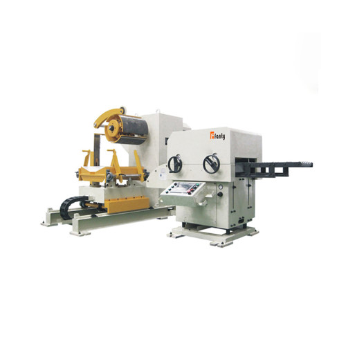
A bracket die near Monterrey asked for 45 mm of feed at 190 strokes a minute, and the 3-in-1 decoiler straightener feeder was rated well above that. The line ran at 190 all week.
It also scrapped 3.2% of the parts, and nobody could say why until somebody measured the feed.
The feed error was 0.09 mm at 190 SPM and 0.04 mm at 140 SPM. Same coil, same die, same operator. The only thing that changed was how long the strip had to settle before the pilots closed.
This is the trade nobody puts on a quotation: on a short feed, accuracy and speed come out of the same budget, and the exchange rate is measurable.
The Number the Die Could Not Hold
The job was 0.8 mm cold-rolled steel, 250 mm wide, four pilots, 45 mm pitch, a simple two-station progressive tool. The part tolerance on hole position was ±0.10 mm.
With a ±0.05 mm feed, half the tolerance is gone before the die does anything. With 0.09 mm of feed error, the pilots are fighting the strip on every stroke.
The scrap showed up as a burr on one edge and an occasional short part. Both symptoms point at the die, which is why the toolroom spent two weeks on a tool that was not the problem.
Feed error hides in plain sight. A short part is obvious. A part that is 0.06 mm long looks fine on a caliper and fails a CMM check three operations later.
The plant only found it because a customer rejected a shipment for hole position, and the quality engineer asked for the feed trace instead of another die inspection.
Where 0.09 mm Comes From at 190 SPM
At 190 SPM the full cycle is 316 ms. The die is closed for about 140 ms of that, which leaves roughly 176 ms for the feed to move 45 mm and settle.
Move time at 6 m/s² acceleration is about 95 ms. That leaves 80 ms of settle, and settle is where the error accumulates, because the strip keeps moving after the command ends.
At 140 SPM the cycle stretches to 429 ms and settle time roughly doubles. The error fell to 0.04 mm without touching a single setting, which told us the machine was capable and the timing was not.
Three things were eating the settle window. Roll pressure was set at 4.5 bar against a 5.5 bar specification, so the strip slipped about 0.02 mm on each acceleration.
The pilot release cam was 15 ms late, so the pilots were still in the strip when the feed command started.
And the in-position window was set at ±0.05 mm, which the drive treated as "arrived" while the strip was still ringing.
Measuring It Without a Metrology Lab
You do not need a laser interferometer. A dial indicator on a magnetic base, a strip of masking tape and a slow-motion phone camera will find the problem in an hour.
Mount the indicator against the strip edge at the die entry, run twenty strokes at production speed, and film the needle. The needle tells you whether the error is random or systematic.
A random spread of 0.03 mm around a stable mean is slip. A mean that walks in one direction is a loop or tension problem. A tight cluster that jumps on every fourth stroke is a pilot timing fault.
Check the strip, not just the machine. Measure thickness at three points across the width. A 0.03 mm thickness variation changes the grip and the feed length at the same time.
Record the numbers at three speeds — 120, 150 and 190 SPM — before changing anything. That curve is the evidence you need to argue for a speed change with production.

Settings That Bought Back 35 SPM
Four changes, all of them free. Roll pressure went to 5.5 bar, acceleration came down from 8 to 6.5 m/s², pilot release advanced 15 ms, and the in-position window tightened to ±0.03 mm.
Slowing the acceleration looks backwards, and it is the change that recovered the most speed. A gentler ramp means less slip, so the strip arrives closer to target and settles faster.
The tighter in-position window cost 8 ms per stroke and removed 0.02 mm of overshoot. Net, the line went from 140 SPM at 0.04 mm to 175 SPM at 0.045 mm.
190 SPM never came back. At that speed the settle window falls under 60 ms and the strip cannot damp out, whatever the settings. The honest ceiling for this die was 175.
That is 92% of the original target, and it runs at 0.6% scrap instead of 3.2%. On a 40,000-part order the material saving alone paid for the measurement afternoon.
What Accuracy Costs in Speed, Feed by Feed
The table below is from this machine after the fixes, running the same 0.8 mm by 250 mm material. Treat the shape as transferable and the numbers as specific to a 1,300 mm line.
| Feed length | SPM holding ±0.05 mm | SPM holding ±0.10 mm | Where it costs you |
|---|---|---|---|
| 25 mm | 165 | 195 | Response time dominates; a heavier strip will not settle at all |
| 45 mm | 175 | 200 | The best zone for this machine, and the hardest to hold once pressure drops |
| 80 mm | 150 | 180 | Velocity starts to matter more than settle |
| 150 mm | 110 | 140 | Loop control becomes the limiting factor, not the feed |
| 300 mm | 75 | 95 | Peak strip speed near 1.1 m/s; the coil brake has to keep up |
Read the table by column, not by row. The gap between the two accuracy columns is the price of tolerance, and it widens as the feed gets shorter because settle time is a fixed cost.
Why Slowing Down Stops Working
Below about 20 mm of feed, response time dominates and no amount of tuning buys accuracy. The servo has to accelerate, move and stop inside a window that is already shorter than its own settling time.
Thin material is the second wall. A 0.4 mm strip has less mass to resist slip, so the acceleration that works on 0.8 mm will mark the surface and still miss position.
Wide strip is the third. A 1,250 mm coil carries far more inertia than a 250 mm one, and the same settings produce a different error curve on the same machine.
Where the measurement misleads. A feed trace taken with the die open says nothing about the run. The pilots, the stripper springs and the die cushion all load the strip at the moment of location.
That is why a machine can hold 0.03 mm on a test stand and 0.09 mm in production, and why the argument about whose fault it is never resolves without a trace taken at the die.
How to Set Your Own Speed Ceiling
Add three numbers and you have the ceiling: fixed response time, move time at your acceleration, and settle time at your accuracy target.
Fixed response is usually 25 to 40 ms on a modern NC straightener feeder. Move time is feed length divided by average velocity, plus the ramp. Settle is 30 to 60 ms depending on strip mass.
Take 45 mm at 6.5 m/s²: response 30 ms, move 95 ms, settle 60 ms. That is 185 ms of feed time, so the cycle cannot be shorter than 185 ms plus the die-closed time of 140 ms.
Three hundred and twenty-five milliseconds gives 184 SPM as a theoretical ceiling. Take 5% off for real-world variation and you land at 175, which is exactly where the line ended up.
- Measure fixed response time with a step command and a scope trace, not from the drive manual
- Calculate move time at the acceleration you will actually run, after slip is under control
- Measure settle time at the accuracy target, because settling to 0.10 mm is faster than settling to 0.03 mm
- Add the die-closed time from the press cycle, measured with a proximity sensor rather than a cam chart
- Take 5% off the result, then quote that figure to production and hold it
If your calculated ceiling is well above the nameplate, believe the nameplate. If it is below, you have found the number to quote to production before they promise a delivery date.
The rest of the error budget — loop, guides, back tension and die geometry — is broken down in the coil line guide library.
How much speed do you lose holding ±0.05 mm instead of ±0.10 mm?
About 25 to 30 SPM on a 45 mm feed, and up to 35 SPM on a 150 mm feed. The cost grows as the settle window shrinks, which is why short feeds are the expensive ones.
Can a 3-in-1 run 190 SPM on a 45 mm feed at ±0.05 mm?
Not on this machine. At 190 SPM the settle window falls below 60 ms and the strip does not damp out. The measured ceiling was 175 SPM, with 0.045 mm of error and 0.6% scrap.
Does lowering acceleration really increase line speed?
Yes, when slip is the error source. Dropping from 8 to 6.5 m/s² removed 0.02 mm of slip per stroke and allowed the line to run 35 SPM faster at the same accuracy.
What roll pressure does a 250 mm strip need?
5.5 bar on this machine, against a 4.5 bar setting that had drifted. Below 5 bar the strip slipped about 0.02 mm per acceleration, which is 40% of a ±0.05 mm budget.
How long does a feed trace take on the floor?
About an hour for three speeds, including setup. Twenty strokes per speed, filmed at 120 frames a second, is enough to separate slip from timing from loop error.
Where to go next
This case sits under the accuracy cluster, where the total tolerance is split between the coil, the loop, the feed and the die.
If your ceiling is lower than the table above, the pillar page will show you which part of the budget is already spent.
Read the feed accuracy error budget