How Much Hydraulic Pressure Does a Decoiler Mandrel Need?
A hydraulic decoiler mandrel needs enough pressure to hold a full coil against back tension, and most nameplates quote a number that is neither measured nor explained. 100 bar is common.
It is not automatically right.
The figure comes from two loads: the coil's own mass hanging on the mandrel, and the torque the brake or drive puts into the strip.
Get the second one wrong and the coil slips on the mandrel at the start of every run, leaving a polished ring and a length error nobody can trace.
Here is the arithmetic, the pressure that comes out of it, and the three coil conditions where the arithmetic stops being reliable.
The Two Loads a Mandrel Has to Beat
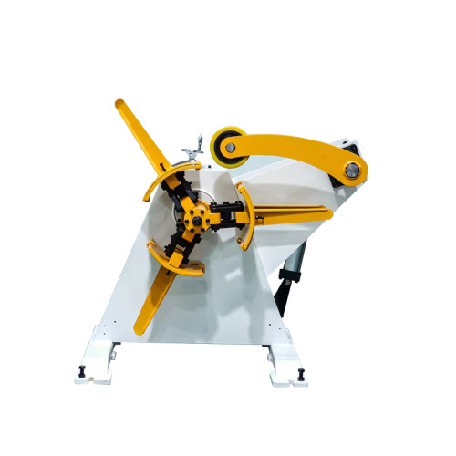
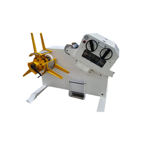
A mandrel is a friction device. It holds a coil by pressing pads against the bore, and everything else about it follows from that.
Load one: coil mass. A 5-tonne coil on a cantilever mandrel loads the front bearing heavily and the pads barely at all. Mass alone does not set expansion pressure.
Load two: torque. Back tension, acceleration and braking all push torque through the coil-to-mandrel interface. This is the load that decides pressure.
The interface only transmits torque through friction. So the radial force has to be large enough that friction, multiplied by the bore radius, exceeds the torque being asked for.
Write it as N = T / (µ × r). Torque in newton-metres, friction coefficient µ, bore radius r in metres, and N comes out in newtons of total radial force.
Two numbers in that expression are always argued about. µ between steel and a steel pad runs 0.12 to 0.18 dry, and closer to 0.10 with oil on the bore. Bore radius is simply half the coil's inner diameter.
Working the Numbers for a 5-Tonne Coil
Take a 5-tonne coil on a 508 mm bore with a 3 kN back tension at a 1,000 mm outer radius. That is a common setup on a 1,300 mm line.
Torque at the mandrel is 3 kN multiplied by the outer radius, so 3,000 Nm. Bore radius is 0.254 m, and µ for an oiled bore is 0.12.
N = 3,000 / (0.12 × 0.254) = 98,400 N, or about 98 kN of total radial force across the pads. That is the number the hydraulic system has to deliver.
Now convert it to pressure. Four pads on a 100 mm bore cylinder each give 7,854 mm² of piston area, and the pads are linked, so the total area is 7,854 mm² for a single-cylinder design.
98,400 N over 7,854 mm² is 12.5 MPa, or 125 bar. A 100 bar nameplate setting is short by 25 percent on this job, which is exactly the margin where slipping starts.
| Coil mass and bore | Pressure to hold 3 kNm | What that pressure costs you |
|---|---|---|
| 3 t on 508 mm bore | 75 bar | Comfortable, but light coils give a poor friction signal at the pads |
| 5 t on 508 mm bore | 125 bar | Needs a 160 bar relief setting and a pump rated above 140 bar continuous |
| 5 t on 610 mm bore | 104 bar | Larger bore lowers pressure but the pad travel has to reach it |
| 8 t on 610 mm bore | 166 bar | Pushes into the range where pad and bore stress matter more than pressure |
The last row is the one to watch. Above about 150 bar the limiting factor stops being the pump and becomes the mandrel wall, the pad hinges and the coil's own bore.
What pressure does a 5-tonne hydraulic decoiler normally run at?
120 to 140 bar working pressure with a 160 bar relief, if the coil runs with meaningful back tension. A machine that never exceeds 90 bar is either lightly loaded or under-gripping.
How much pressure drop over 5 minutes means a leaking seal?
More than 5 bar from a 120 bar set point with the coil static. A healthy circuit holds within 2 bar once the oil is at temperature.
At what bore size does a standard mandrel stop expanding?
Below 400 mm bore most segmented mandrels run out of pad travel. A 300 mm bore coil usually needs a different mandrel body rather than more pressure.

Why Nameplate Pressure Is Not Working Pressure
The gauge at the valve block does not read what the pads see. Three losses sit between them, and each one is worth 5 to 15 bar.
Line and fitting losses. A 6 mm hose run at 6 L/min loses 3 to 8 bar, more if the oil is cold and the viscosity is high.
Relief valve setting. A relief set at 160 bar does not hold 160 bar. It cracks early and passes oil, so the working figure is usually 10 percent below the setting.
Temperature drift. Oil at 20 °C and oil at 55 °C behave differently in the same circuit. Pressure holds; response slows, and slow expansion reads as insufficient pressure on a short cycle.
There is also the mechanical side. A mandrel with worn pad hinges loses force to friction before the pad ever touches the bore, and no amount of pump pressure recovers it.
This is why a machine that grips perfectly when new starts slipping at eighteen months without any change to the gauge reading. The pressure is the same and the force at the bore is not.
The gauge's own error. A 0 to 250 bar gauge at 2.5 percent accuracy is worth ±6 bar at the reading, which is enough to hide a slipping condition on a light coil. Fit a 0 to 160 bar gauge on mandrel circuits.
Cold oil. Below 15 °C the oil is thick enough that expansion takes four seconds instead of two, and an operator watching for movement reports a pressure fault that is really a temperature fault.
Where the Arithmetic Breaks Down
The formula assumes a round bore, a stiff coil and a pad that contacts evenly. Real coils break all three assumptions, and the failures are predictable.
Paper and wooden cores. A fibre core compresses under pad load, so the effective pressure at the steel is lower and the bore deforms. These coils need wider pads, not higher pressure.
Thin-wall or oval bore. A coil that has sat on a flat floor for a month is no longer round. Three pads touch and one does not, so the contact area drops by a quarter while the gauge reads normal.
Collapsed or telescoped coil. The wraps have already moved against each other. No mandrel pressure will restore the coil, and forcing it damages the bore and the pads together.
Very small bores. Below 400 mm the pad travel limit arrives before the force limit. Adding pressure to a mandrel that cannot reach the bore just loads the hinges.
There is one more case that misleads people: a coil that slips only in the first two metres.
That is usually a dry bore and a cold circuit, not an under-pressured mandrel, and raising pressure hides the symptom without fixing it.
Testing Expansion Without Stripping the Coil
You can check grip without dismantling anything. Five checks, twenty minutes, and a pressure gauge you already have.
- Load a coil, expand at the normal setting, and mark the bore and the mandrel pad with a paint line across both.
- Run the first 20 m with full back tension, then stop and look at the marks. Any offset is slip, measured directly.
- Hold 120 bar with the coil static for five minutes and log the drop. Above 5 bar, the seals or the check valve are suspect.
- Feel each pad by hand after expansion. A pad that rocks under thumb pressure is not carrying its share of the load.
- Measure the oil temperature at the tank, not at the valve. Above 55 °C the circuit is losing response before it loses pressure.
The paint-mark test is the one worth institutionalising. It answers the question in one run and leaves a record on the coil that anyone can read.
Sizing the Pump, the Tank and the Cycle
Pressure is only half the specification. A pump that reaches 140 bar slowly is as much a problem as one that reaches 110 bar quickly.
Flow. Four pads moving 8 mm each on a 100 mm bore need about 0.25 L of oil. A 6 L/min pump fills that in under three seconds, which is fast enough for a coil change.
Motor size. At 140 bar and 6 L/min the hydraulic power is 1.4 kW, so a 2.2 kW motor leaves sensible margin without oversizing the starter.
Tank volume. Three times the pump flow is the working minimum, so 20 L for a 6 L/min unit. Smaller tanks heat faster and the pressure drifts with temperature.
Accumulator. Not always fitted, and worth having on a line that changes coils more than ten times a shift. It holds pressure during the change instead of re-priming the circuit each time.
An accumulator adds $600 to $1,200 to the build and about fifteen minutes to the annual service.
On a line changing coils eight times a shift it removes the pressure dip that shows up as a slack coil at every change.
Base dimensions, mandrel travel and pump options for our builds are listed in our decoiler data library, the drawing set to open before a pressure is specified.

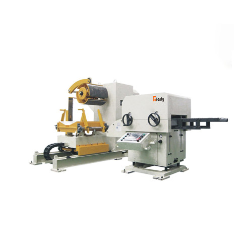
A decoiler and a plain uncoiler are sized by the same bore arithmetic, so the calculation above transfers directly to a motorised uncoiler with a mechanical brake. Only the torque term changes.
Where to go next
Pressure is one line in a specification that runs from coil mass to control type, and the order those decisions are made in matters more than any single value.
The coil line guide library sets out the full specification chain for a decoiler, from capacity through mandrel to control, so a pressure figure lands in the right context.