How Does Perforated Strip Behave in a Servo Feeder?
The line ran 1.2 mm CR louvre panels at 180 SPM and held 0.05 mm for three weeks. Then the customer switched to a perforated pattern with 38 percent open area.
Within 200 strokes the same NC servo feeder was losing 0.3 mm of feed length. Nothing on the machine had changed.
This is the account of what we found, because the cause was not slip in the ordinary sense and the usual fixes made it worse.
The Job That Started the Call
The part was a ventilation panel, 300 mm wide, 5 mm holes on an 8 mm pitch, running through a progressive die with two pilots per station.
Feed length was 42 mm with a tolerance of plus or minus 0.15 mm. The line held it comfortably on solid strip.
On the perforated pattern, the first 150 strokes were fine and then the length walked downward, 0.05 mm at a time, until the pilot started clipping the hole edge.
The operator did what the manual says. He raised roll pressure. The drift got worse, the holes around the feed line deformed, and the die picked up a burr on the pilot.

What 38 Percent Open Area Does to Grip
Two things change when the strip is perforated, and just one is obvious.
The obvious one is contact area. A feed roll that pressed on 300 mm of solid strip now presses on about 62 percent of that, so the friction force available to accelerate the strip falls by roughly a third.
The less obvious one is that the roll no longer runs on a cylinder. Where a hole passes under the roll, the roll surface drops into it by up to a millimetre before the next land picks it up again.
That drop changes the effective radius of the roll, and feed length is delivered as rotation times radius.
A 200 mm roll that drops 1 mm delivers 0.4 mm less per 42 mm feed, which is almost exactly the drift we were seeing.
Raising pressure makes this worse rather than better. More pressure pushes the roll deeper into the holes, deforms the hole edge, and wears the roll surface into a pattern that matches the perforation.
The Measurement That Settled It
We proved the radius theory with a marker pen and a hundred strokes, which took twenty minutes and no instrumentation.
Mark the feed roll across its face, run a hundred strokes, and measure the distance between the first and last mark on the strip.
If the roll is running on solid strip, that distance equals a hundred times the feed length.
Ours came up 12 mm short over 4.2 metres, which is 0.12 mm per stroke on average and matched the observed walk.
The same test with the perforated strip rotated so a solid land ran under the roll recovered most of the difference.
That last result was the useful one. It meant the pattern position relative to the roll mattered, which is a setup problem rather than a machine limitation.
Three Strip Conditions, Three Different Faults
Perforated work fails in more than one way, and the fix depends on which way yours is failing. The table separates them by what the roll actually experiences.
| Strip condition | What the roll sees | Where it costs you |
|---|---|---|
| Holes under the roll, no land | Falling effective radius, 0.3 to 0.5 mm per 40 mm feed | Feed length walks until the pilot clips; correcting it in the control hides a mechanical cause |
| Open area above 55 percent | Insufficient contact to accelerate the strip at all | Double feeds and short feeds in the same shift, which reads as a control fault |
| Hole edge burr left by the perforator | Local pressure peaks that mark the roll face | Roll wear in a pattern, then permanent marking on every later job |
| Thin perforated stock below 0.8 mm | Hole distortion before the strip moves | Scrap at the pilot station, blamed on the die |
Our case sat in the first row with a touch of the third, which is why pressure alone could never have fixed it.
Why Pilot Release Timing Hid the Problem
The die was releasing the pilots late, which is a normal setting for a heavy progressive job and a bad one for perforated strip.
With a late release, the pilots hold the strip while the feed rolls are already trying to advance it.
The rolls then slip against a stationary strip, and the slippage is not repeatable, so the error looks random rather than systematic.
Advancing the release by 15 degrees of crank angle removed that conflict. The drift did not disappear, but it became consistent, and a consistent error can be compensated.
What We Changed on the Machine
Four changes, in the order they were made, with the effect each one produced.
Pattern orientation. The coil was rotated so a 12 mm solid land runs under the feed roll. This recovered about 0.2 mm of the 0.3 mm error and cost nothing but a setup note.
Roll pressure. Reduced from 4.5 bar to 3.2 bar. Counter-intuitive, but with the land under the roll the extra pressure was only pushing the roll into the remaining holes.
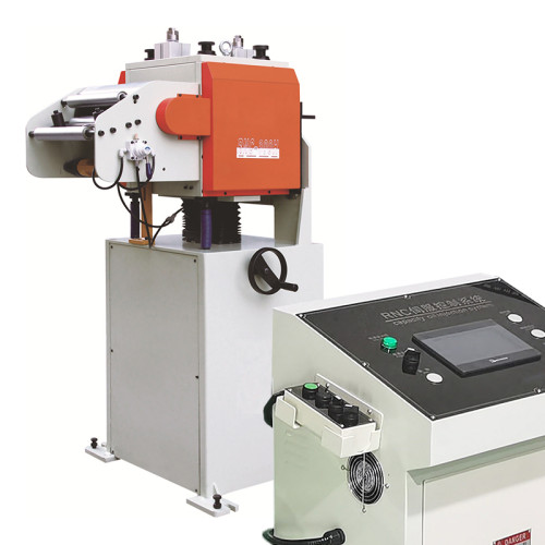
Polyurethane roll. A 70 Shore A roll replaced the steel one on the upper shaft. It conforms around the hole edges instead of dropping in, and the residual drift fell below 0.05 mm.
Acceleration limit. Ramp reduced so the strip reaches speed over 12 mm instead of 8. At 180 SPM this costs about 4 percent of theoretical output and removed the last of the random short feeds.
Written as a change order, the sequence matters more than the individual items.
- Orient the pattern first, because it changes the pressure that is needed afterwards.
- Set pressure from a strip-pull test, not from the setting used on solid stock.
- Change the roll compound only after the first two steps, or you will not know which one worked.
- Leave the acceleration ramp for last, since it is the only change that costs output.
Where This Fix Stops Working
The combination above holds on 1.2 mm CR at 38 percent open area. It does not generalise, and three boundaries are worth stating before anyone quotes a similar job.
Above 55 percent open area there is not enough continuous material for any roll to accelerate reliably. At that point the answer is a different feeding principle, not a different roll compound.
Polyurethane wears quickly against a burred hole edge. On a two-shift perforated job we now expect a roll change every 10 to 14 weeks, which is a consumable cost that belongs in the quote.
And compensating drift in the control is a trap. If the servo feeder is told to add 0.3 mm to every stroke, it will keep adding it after the die is re-ground and the pattern has moved.
The correction has to be re-proven at every tool change, not set once.
What to Check Before Quoting Perforated Work
Five questions, asked before the quote rather than after the first production run.
- What is the open area, and is there a continuous land at least 10 mm wide anywhere across the width?
- What is the hole diameter against the feed length, because a 3 mm hole on a 6 mm pitch behaves differently from 5 mm on 8 mm.
- Can the pattern be oriented so a land runs under the roll without breaking the die layout?
- What burr height does the perforator guarantee, since anything above 0.05 mm starts marking the roll.
- How much output can the job afford to lose to a longer acceleration ramp?
An NC servo feeder with a 200 mm roll is a good match for most perforated work up to about 40 percent open area. Above that the limitation is the feeding principle, and no amount of tuning will move it.
How much feed length does a 1 mm drop into a hole cost on a 200 mm roll?
About 0.4 mm on a 42 mm feed, which is 1 percent. On a 300 mm roll the same drop costs 0.28 mm, which is why larger rolls are more forgiving on perforated strip.
Is 55 percent open area really the ceiling for roll feeding?
For steel rolls, yes, in our experience. Between 40 and 55 percent a conformable polyurethane roll can hold 0.1 mm, and above 55 percent we have not seen a roll-based solution hold tolerance.
How often does a polyurethane feed roll need replacing on perforated work?
Every 10 to 14 weeks on two shifts with a burred hole edge, and 20 to 26 weeks if the perforator holds burr under 0.03 mm.
Can the control compensate for a walking feed length?
It can, up to about 0.3 mm, but the correction must be re-proven at every die re-grind. A stored offset that outlives the tool becomes a new error.
Does pilot release timing matter as much as roll pressure?
On perforated strip it matters more. Fifteen degrees of late release turns a systematic error into a random one, and a random error cannot be corrected.
At what thickness does perforated strip stop being feedable at all?
Below 0.6 mm with open area over 30 percent, the strip distorts before it moves. We would not quote a roll-fed line for that combination without a trial.
The error budget that governs this class of problem, from the coil through to the die, is set out in our coil line knowledge base.
Roll diameters and drive options for each model are listed in the machine specification pages.
Where to go next
Perforated strip is one entry in a longer list of conditions that move feed length. The accuracy pillar separates each contribution and shows which ones a machine change can remove.
Work through the feed accuracy budget