How Do You Square a Decoiler to the Press Centreline?
A decoiler that sits 1 mm out of square per metre puts the strip 5 mm off centreline at a die five metres away. No edge guide absorbs that, and the operator spends the shift blaming the coil.
Squaring is the first alignment job on any coil line and the one most often skipped, because the machine looks straight and the anchor bolts are already tight.
Here is the sequence we use on commissioning, in the order that works.
Why Squaring Decides Strip Tracking Before Anything Else Does
Tracking problems get blamed on the edge guide, the straightener roll alignment, or the coil itself. Nine times out of ten the error started at the base of the decoiler.
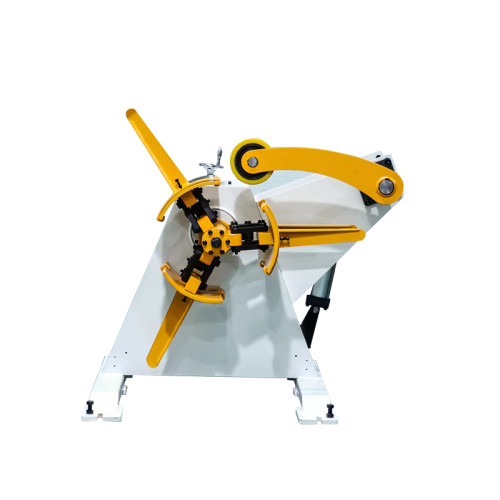
A decoiler holds a coil on a cantilevered mandrel. Any angular error at the base is multiplied by the distance from the mandrel to the first guide roll. That multiplication is the whole problem.
Lateral error compounds with distance. Half a millimetre per metre sounds like nothing. Across six metres of line it becomes 3 mm of steady side load on the strip edge.
Height error changes the payoff angle. A mandrel axis 8 mm high pulls the strip up into the first roll and changes the entry angle through the straightener. Flatness suffers before tracking does.
Level error loads one side of the mandrel bearing. A decoiler that is 0.5 mm out of level over its base width carries a continuous axial thrust that no bearing preload is designed for.
None of those three faults shows up as a decoiler fault. They show up as edge damage, wavy strip, and a bearing that fails at eighteen months instead of five years.
The cantilever is the amplifier. A 1,300 mm wide coil on a mandrel held at one end is a lever. A tenth of a millimetre of slack at the base flange becomes half a millimetre of swing at the coil face.
That swing reverses every time a coil comes off and a new one goes on.
The strip therefore enters the line from a slightly different angle each coil, which is why tracking complaints are intermittent rather than constant.
The Five Measurements That Define a Square Installation
Five numbers settle the job. Take them with the coil off the mandrel and the machine unloaded, then repeat with a coil on to see how the base reacts.
| Measurement | Working target | Where it costs you when it drifts |
|---|---|---|
| Mandrel axis to line centreline, lateral | ±0.5 mm over the first metre | Steady side load on the strip edge; the edge guide fights it all shift |
| Mandrel axis height against pass line | ±2 mm | Entry angle changes; flatness and feed length both drift |
| Base level across the width | 0.05 mm per metre | Axial thrust on the mandrel bearing, uneven anchor load |
| Base square to the line, in plan | 90° ±0.05° | Strip runs diagonally; camber appears that the coil does not have |
| Payoff point to first guide roll | Per layout, ±10 mm | Loop shape changes, and the loop control hunts at low speed |
Two instruments do all of it: a machinist level reading 0.02 mm per metre, and a tensioned piano wire or a laser on the line centreline. A tape measure and a spirit level will not find these errors.
Record the five numbers on a sheet that goes into the machine file. Two years later, when a tracking complaint arrives, that sheet is the only way to know whether the base moved or the coil changed.

How to Set the Datum and Work Outward
Work from the die backwards, not from the wall forwards. The die cannot move, and every metre of accumulated error lands on the machine furthest from it.
- Stretch the centreline wire through the die bore and anchor it at both ends, above the pass line.
- Level the base across the width first, using shim packs under the sole plates, never under the frame.
- Set the mandrel axis parallel to the wire with a dial indicator on a swinging arm, reading both ends.
- Confirm the height of the mandrel axis against the pass line at the payoff point, not at the machine frame.
- Grout or torque the anchors only after all four readings pass, then repeat the whole set.
- Load a full coil and re-read level; a base that moves 0.1 mm under load needs a stiffer foundation.
The order matters more than the instruments. Level before square, square before height, and anchors last. Doing it the other way means unbolting a machine that is already grouted.
Keep the shim stack thin. Three plates under a sole plate is the practical limit. A 15 mm stack of loose shims compresses under load and takes the alignment with it.
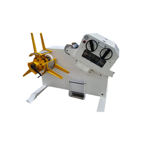
A decoiler and a plain uncoiler are squared the same way. The drive package changes what happens after the strip moves; it changes nothing about the geometry.
On a line we commissioned for an appliance stamper in 2024, the base sat 0.7 mm out over 900 mm. The edge guide was working through 4 mm of correction at the die and burning through guide plates every six weeks.
Two hours of shimming ended an eighteen-month complaint.
Where Squaring Cannot Fix a Tracking Problem
A square decoiler removes one class of tracking error. It does not remove the others, and blaming geometry for them wastes a shift.
Camber in the coil itself. Mill camber of 5 mm over 5 m follows the strip regardless of how well the mandrel is aligned. You can guide it or you can reject it.
Slit coil with uneven burr. A slit edge with 0.15 mm of burr on one side steers the strip like a rudder. No amount of alignment corrects a burr that is not symmetric.
Edge guide range. Most guides correct ±3 to ±5 mm. A layout error of 8 mm is outside that range, and the guide will simply pin the strip against one side.
Foundation movement. A slab that settles 2 mm over two years takes the decoiler with it. Squaring is not a one-time event on a soft floor.
On a decoiler carrying 5 tonnes on a cantilever, the structural deflection under load is real and measurable.
Expect a few tenths of a millimetre at the mandrel nose and allow for it in the target rather than chasing zero.
What to Re-Check After the First Ten Coils
The first ten coils load the machine harder than any acceptance test. Ten coils is the point where a base that was going to move has moved.
Re-read level across the base and along the mandrel. Re-check the anchor torque against the foundation drawing, because grout cures and shim packs compress.
Then read the strip, not the machine. Run a 3-metre length through the guides with no forming and measure the lateral drift at the far end. That single number tells you whether the geometry held.
Two of the three faults that appear in the first month trace back to installation rather than manufacture.
That is why we send the alignment sequence with the machine, and why the commissioning report records all five readings rather than a tick box.

What the Floor Has to Give the Base
A decoiler does not just sit on a slab. It loads one edge of its footprint far harder than the other, and a floor that carries the weight may still fail the moment.
The overturning moment dominates. A 5-tonne coil on a 900 mm mandrel creates a load that concentrates on the two anchors nearest the coil. Those two anchors do most of the work.
Slab thickness matters more than concrete grade. A 200 mm reinforced slab at 25 MPa is normal for this duty. A 120 mm floor needs a spreader plate sized by the machine supplier, not by the builder.
Grout is structural. Non-shrink grout at 25 to 50 mm fills the gap between sole plate and slab and spreads the load. Machines bolted straight to an uneven floor lose alignment within a season.
Model base dimensions, anchor patterns and recommended plate sizes are listed on the machine specification pages in our coil handling product index.
Check the drawing against the floor before the concrete is poured, not after.
We have installed more than 200 lines, and the alignment complaints we investigate almost always trace back to a base that was never given a flat, stiff surface to sit on.
Is 1 mm per metre enough misalignment to spoil tracking?
Beyond 0.5 mm per metre of run to the first guide, edge wear becomes measurable. At 1 mm per metre the guide is permanently correcting and plates wear out in weeks.
What level tolerance should a 200 mm foundation slab meet?
2 mm over the full footprint before grouting. Shim packs handle the rest, but a slab out by 10 mm needs levelling compound, not shims.
Does a 5-tonne coil change the squaring procedure?
The procedure is identical, but every reading is taken twice: unloaded and with a full coil. A base that shifts more than 0.1 mm under load needs a thicker sole plate.
Where to go next
Alignment is the last step of a specification decision that starts much earlier.
The capacity, type, mandrel and control choices for a decoiler are set out in the cluster guide at the coil line guide library, and a machine specified against those four points is far easier to square on site.