How to Set an NC Straightener Feeder for Gauge Drift?
A coil that measures 0.80 mm at the head, 0.76 mm in the middle and 0.83 mm at the tail will not run flat on a single penetration setting, no matter how carefully that setting was chosen.
Cold-rolled gauge is not constant. Mill tolerances allow a band, the head and tail run thick, and a weld joint puts a step through the roll stack in one stroke.
An NC straightener feeder is usually set once, from a drawing, and then blamed for flatness that changes along the coil.
This works the arithmetic on how much a 0.05 mm gauge change moves the bend, and gives a setting routine for coils that carry a band rather than a number.
Where Gauge Drift Comes From
Four sources put a thickness band on a coil, and only one of them is a mill defect.
The mill tolerance itself. EN 10131 allows ±0.05 mm on 0.80 mm cold-rolled strip in the normal tolerance class, which is a 12.5 percent band before anything goes wrong.
Head and tail thickening. The first and last 20 to 40 m of a coil typically run 0.02 to 0.04 mm above nominal, because the rolling force has not settled or is coming off.
Weld joints. A coil built from two mill coils carries a weld with a thickness step. A good weld is within 0.05 mm; a poor one reaches 0.15 mm and will lift the rolls.
Measured versus nominal. The coil certificate quotes a nominal with a tolerance, and the actual strip is somewhere inside it. Nobody measures it unless flatness already failed.
The consequence is that a setting derived from the drawing is a setting for a thickness that may not exist anywhere on the coil.
How to measure it. A point micrometer with 0.001 mm resolution, six readings at each of three stations. A caliper is not good enough at 0.80 mm, because jaw flex alone is worth 0.02 mm.
Where to measure. 25 mm in from each edge and on the centreline. Edge readings run 0.01 to 0.02 mm thin on a slitter-trimmed coil, which matters when the die uses the full width.
When to measure. At goods-in, before the coil goes into the rack. A coil measured after three months of storage carries the same gauge and a different surface, and the two faults get blamed on each other.
How 0.05 mm Changes the Bend
Penetration is set as a fraction of thickness, so a fixed penetration on a drifting gauge is a changing strain ratio. That ratio is what decides flatness.
Take a 0.80 mm strip with penetration set at 0.32 mm, which is 0.40 t. That is a normal working value for a five-roll head on 280 MPa yield strip.
Run 0.75 mm strip through the same setting and 0.32 mm becomes 0.427 t. The bend is 6.7 percent deeper than the setting intended, and the strip leaves with a reversed curvature at the exit.
Run 0.85 mm strip and 0.32 mm becomes 0.376 t. The bend is 6 percent shallower, the strip is not fully yielded through the section, and residual bow survives to the die.
Both errors land in the same place: a flatness change of roughly 5 to 8 I-units across the coil, which is the difference between a passing panel and a rejected one on a visible surface.
The direction of the error depends on which side of nominal the gauge sits, which is why the same coil can bow upward at the head and downward at the tail.
| Gauge zone | What the fixed setting does | What it costs downstream |
|---|---|---|
| 0.75 mm, thin middle | 0.32 mm is 0.427 t, an over-bend | Centre buckle, and roll marking from excess pressure on a thin section |
| 0.80 mm, nominal | 0.32 mm is 0.40 t, on target | Nothing, which is why the fault hides in the middle of the coil |
| 0.85 mm, thick head | 0.32 mm is 0.376 t, an under-bend | Residual bow of 0.15–0.3 mm over a 1 m sample |
| Weld with a 0.15 mm step | Rolls lift and the strip is not bent at all | A short length of unstraightened strip, plus a roll load spike |

Setting the Rolls for the Coil You Actually Have
The routine has three steps, and the first one is a micrometer rather than a keyboard.
Measure the band. Take six readings along the coil at the head, middle and tail, on both edges and the centre. Ten minutes gives you the real thickness range instead of a nominal.
Set to the thin end, not the nominal. Penetration set for the thinnest zone means the thick zone is slightly under-bent rather than the thin zone being over-bent.
Under-bend is recoverable with back tension; over-bend marks the strip.
Use back tension to close the gap. Two to four kN of back tension on the entry side pulls the strip against the entry roll and recovers most of the residual bow that an under-bend leaves on the thick zone.
Open the last pair slightly. The finishing pair controls surface and straightness in the pass line. Setting it 0.02 mm above nominal gap reduces marking on the thin zone without changing the bend upstream.
Log the setting per coil, not per part. A recipe that carries gauge range as well as gauge nominal tells the next operator what to expect before the first stroke.
On the coil in this example, setting to 0.75 mm and adding 3 kN of back tension held flatness inside 3 I-units across the whole length, where the nominal setting had varied from 2 to 11.
Limits the Roll Stack Cannot Absorb
There is a gauge band beyond which no setting routine helps, and it is worth stating where that edge sits.
Steps, not slopes. A weld with a 0.15 mm step is not a gauge variation, it is a discontinuity. The rolls must open for it, and that short length runs unstraightened whatever the recipe says.
Bands wider than 0.12 mm. Once the range exceeds about 15 percent of nominal, one setting cannot serve both ends. The answer is two coils or a gauge-based control, not a cleverer penetration value.
Gauge that changes across the width. A strip that is 0.82 mm on one edge and 0.76 mm on the other is a rolling defect, not a coil variation.
No straightener removes a wedge, and forcing penetration to fix one edge buckles the other.
Where the arithmetic misleads. A flatness reading taken on a 300 mm sample can look acceptable while the coil as a whole is not, because the sample may come from the nominal zone that the setting was designed for.
State the boundary honestly to a customer: a straightener widens the process window, it does not remove the mill tolerance that defines the window.
A Setting Sheet for Two-Gauge Coils
When a plant runs two gauges from one head, the setting sheet does more work than the machine. Four lines cover it.
- Record the measured band per coil, not the nominal from the certificate.
- Set penetration from the thin end and note the thick-end residual in the recipe.
- Enter the back tension figure with the penetration, because the two settings only work as a pair.
- Flag any coil with a weld in the run sheet so the operator opens the rolls for the joint.
- Re-check flatness at the head, middle and tail, not once at the start of the run.
| Setting approach | What it fixes | What it leaves you with |
|---|---|---|
| Penetration from nominal | Nothing on a drifting coil, and it looks correct on paper | Bow at one end, buckle at the other |
| Penetration from the thin end | Removes over-bend and marking on the thin zone | Residual bow on the thick zone until tension is added |
| Thin end plus back tension | Closes most of the residual bow without touching penetration | Needs a tension figure in the recipe, and a brake that holds it |
| Gauge-based control | Tracks the band automatically | A capital item, and still no answer to a weld step |
How much gauge variation does a standard CR coil carry over 5 tonnes?
0.05 to 0.08 mm on a 0.80 mm nominal, with the widest spread at the head and tail. A coil built from two mill coils adds a weld step on top of that.
Does a 0.05 mm gauge change cost 1 I-unit or 8?
Roughly 5 to 8 I-units when the penetration is fixed, because a 6 percent change in strain ratio is enough to move the strip from fully yielded to partly elastic at the exit.
Can a 5-roll head hold flatness across a 0.1 mm gauge band?
Only with back tension and a thin-end setting. A nine-roll head carries about twice the correction range, which is why heavy gauge work moves up in roll count rather than in pressure.
What happens at a weld joint with a 0.15 mm step?
The rolls lift, the load spike reaches two to three times normal, and 200 to 400 mm of strip passes unstraightened. Open the gap by 0.3 mm for the joint and close it again after.
Roll counts, diameters and penetration ranges for our heads are listed in the straightener data sheets, and the roll count is the number that decides how wide a gauge band a head can serve.
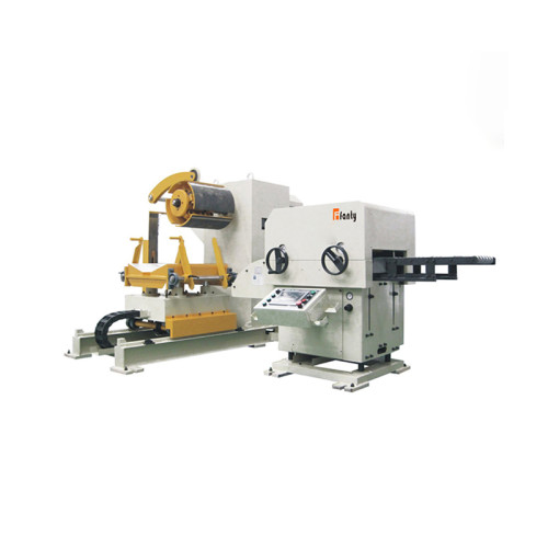
Flatness from a 3-in-1 decoiler straightener feeder is only as good as the spec it was set against. That guide treats roll count, pitch, gap and penetration as one system rather than four dials.
Where to go next
Gauge drift is the input most flatness arguments ignore, because it is easier to adjust a roll than to measure a coil.