How to Set Up Die Protection on a Coil-Fed Press?
Half past two on a Tuesday, and a 160 t press has just put a pilot punch through the bottom of a die that was rebuilt six weeks earlier. The operator saw nothing wrong. The strip looked fine, the NC servo feeder reported no alarm, and the press cycled exactly as it had for the previous four hundred strokes. What happened between the last good part and the wrecked die was a short feed of about 6 mm — small enough to hide, large enough to destroy tooling.
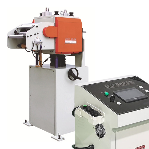
Die protection exists to catch that 6 mm before the ram comes down. Setting it up properly on a coil-fed press is a sequence, not a switch, and the order in which you do the steps matters more than the sensors you buy. If the feeding equipment itself is still being selected, start from the NC servo feeder range and come back to protection once the machine is chosen.
What the System Has to Catch Before the Die Does
A die protection system is not a safety circuit and it is not a quality gauge. It is a set of conditions that must be true for the press to be allowed to make the next stroke. On a coil-fed line the conditions fall into four groups, and a setup that covers three of them will still let a die break.
- Strip present and correctly positioned. The strip must actually be under the sensors and at the right station when the ram reaches the point of no return.
- Feed completed before the stroke begins. The feeder has to signal that the commanded length is finished, not merely that it started moving.
- Previous part ejected. A slug or a finished part sitting in the die blocks the strip just as effectively as a short feed.
- End of coil handled. The tail of the coil is the single most dangerous moment on a coil line, because a half-fed strip can look present at every sensor while holding nothing.
Everything below is about making those four conditions reliable at production speed rather than at the speed you first commissioned the line.
Steps One and Two: Sense the Strip, Not the Ram
The first decision is where the sensors look, and the answer is never “at the ram”. Ram position tells you where the press is, not where the material is. The material is what moves.
Step one: choose sensing points that match your failure modes. A die protection setup usually needs three to five points on a coil line, not one. Put a probe where a short feed will show up first — typically the last idle station before the first working station — and add one at the scrap chute and one at the part exit if the die runs a slug that can back up.
Step two: pick the sensor type for the space you have. Inductive proximity sensors are the default because they survive oil mist and chips. Photoelectric sensors suit thin strip and tight spaces but need the lens kept clean. Mechanical probes are the last resort, useful where nothing else fits, and they wear.
| Sensing point | Typical sensor | Catches | Watch out for |
|---|---|---|---|
| Idle station, before first working station | Inductive proximity, 4 mm sensing | Short feed, missing strip, strip bow | Needs a clean hole or feature to detect |
| Part exit / chute | Photoelectric, through-beam | Part not ejected, double part | Oil film on the lens causes false stops |
| Scrap chute | Inductive proximity or photoelectric | Slug backup, blocked chute | Mounting must survive vibration |
| Strip edge, before the die | Photoelectric edge or laser | Strip running off-centre, camber | Alarm threshold needs to ignore normal camber |
| Coil tail | Loop or proximity on the decoiler | End of coil reached | Must stop the press before the tail leaves the rolls |
Two rules hold regardless of the sensor list. Mount every sensor on the die or on the lower shoe, never on a bracket that hangs off the press frame, because relative movement between the two is exactly what you are trying to measure. And keep the number of sensors to the number of failure modes you have actually seen — a system that stops the press twice a shift for no reason will be bypassed within a week, and a bypassed system protects nothing.

Step Three: Get the Signal Into the Press Control
This is where most homemade setups fail, and it fails quietly. A sensor that switches a relay which switches a contactor has added between 15 and 40 ms of delay to the chain. At 200 SPM a press travels about 10 mm of crank angle in 20 ms, and the difference between stopping before bottom dead centre and stopping after it is measured in single milliseconds.
Wire the sensors into the press control's die protection input, not into a general stop circuit. The dedicated input is designed to be evaluated inside the stroke window and to stop the ram at the earliest possible angle. A general stop drops the clutch but lets the flywheel energy carry the ram through the rest of the stroke.
Three wiring habits pay for themselves. Use shielded cable and earth the shield at the control end only, because an unshielded sensor run alongside servo drive cabling will pick up noise and produce phantom stops. Give the die protection circuit its own fused supply so a fault in one sensor cannot take down the whole press. And label both ends of every conductor with the sensing point it belongs to, because the person who has to fault-find the circuit at 2 a.m. will not be the person who installed it.
If the feeder is a servo unit, also take the feed-complete signal from the feeder into the press control rather than relying on a timer. A timer set to the average feed time will pass a short feed and fail a slow but correct one.
Step Four: Time the Stop Against Pilot Release
Die protection and pilot release interact, and getting the interaction wrong produces a press that either stops for no reason or does not stop when it should.
Pilot pins enter the strip to locate it before the working stations cut. The strip must be free to be pushed by those pilots, which means the feed rolls have to release at the right moment. Release too early and the strip is loose before the pilots have hold of it, so a short feed can still be pushed into position and hide. Release too late and the pilots push against a gripped strip, which bends the pilots and drags the strip.
The setting that works on most progressive dies is release beginning just after the feed completes and full release before the pilots touch the strip. On a mechanical press this is normally controlled by a cam; on a servo feeder it is a programmable output. Either way, verify it with the press on inch and the strip marked, not by watching the finished part.
One practical check: put a mark on the strip at the pilot position, inch the press through a full cycle, and look at where the mark ends up. If the strip has moved after the pilots engaged, the release timing is late.
Step Five: Prove It Without Scrapping a Coil
A die protection system that has never been triggered is an untested system. The proof is simple and it takes less than an hour.
Run the line at production speed with good material and let it settle. Then introduce one fault at a time and confirm the press stops. Disconnect the strip-present sensor. Block the part exit. Slide a piece of strip into the scrap chute. Shorten the feed by 5 mm through the feeder program. For each fault, record two things: that the press stopped, and where in the stroke it stopped.
If the press stops after bottom dead centre on any of those tests, the fault is in the timing or the wiring, not in the sensor. Fix it before production, because a die protection system that stops late is worse than none at all — it gives the operator confidence that the die is protected when it is not.
Write the results into the setup sheet with the date. With more than 200 coil lines installed across 60+ countries, the shops that keep that record are the ones that can prove, two years later, why a particular die never broke.
The Checks That Get Skipped, and What They Cost
Four habits account for most die protection failures in the field, and none of them is a hardware problem.
Sensors mounted on the upper shoe. It looks tidier and it halves the wiring run, but the upper shoe moves relative to the strip on every stroke. Sensors must see the strip from a fixed reference. Move them to the lower shoe or the die block.
Thresholds set on a running press. Adjusting sensitivity while the press cycles produces a setting that passes the part in front of you and fails the one that comes off a slightly different part of the coil. Set thresholds on inch, then run production and confirm.
No bypass log. Every shop has a night shift that bypasses a nuisance sensor to keep running. Without a log, the bypass becomes permanent. Require a written entry and a signature, and require the sensor to be reinstated before the next shift starts.
Why the Coil Tail Is the Riskiest Moment
The tail is where most coil-line die damage happens, because the strip is short, light and easy to mis-feed, and because everyone on the floor is watching the changeover instead of the tool.
Two mechanisms cause it. As the coil runs down, the remaining wraps lose the weight that kept them pressed together, so the strip can lift and wander in the pass line. And when the tail finally clears the entry guides, the strip is no longer held at both ends — it is free to be pushed sideways by the feed rolls, and a strip that moves sideways at the first station arrives at the working stations at an angle.
The fix is a margin, not a sensor. Set the coil-end signal to stop the press with at least two strokes of strip still in the rolls, and plan the changeover around that margin rather than around the last possible part. On a 250 mm feed that is 500 mm of usable strip written off, which is cheaper than one damaged pilot. Shops that chase the last part from every coil are the ones that replace tooling most often.
None of this requires a bigger budget. It requires doing the five steps in order, testing them at production speed, and writing down what the test showed.
How many sensors does a coil-fed press actually need?
Most progressive dies need three to five on a coil line: one strip-present point before the first working station, one at part exit, one at the scrap chute, and one coil-end signal from the decoiler. Add a fifth only if you have a specific failure mode that the first four cannot see.
Can a servo feeder signal replace strip-present sensing?
No. The feeder knows it commanded a length and finished the motion; it does not know the strip arrived. Roll slip, a broken strip or a mis-set roll gap can all produce a completed feed command with the strip still short. The two signals are complementary.
Why does the press stop on a good part during the first shift?
Almost always a threshold set too tight for normal variation. Strip camber, thickness tolerance and coil set all move the strip slightly within the pass line. Set the window from a run of at least 200 good strokes, not from a single part held in front of the sensor.
Does die protection replace a misfeed detector on the feeder?
They cover different failure modes. A feeder misfeed detector watches the drive and the roll motion; die protection watches the material in the tool. A line with only one of the two will still break a die eventually.
How often should the stop timing be re-verified?
After any change to the press control, the feeder program, the die setup or the pilot release cam. Also once a year as routine, because contactor and relay response times drift with age, and 10 ms of drift is enough to move the stop point past bottom dead centre.
Building die protection into a new coil line? Tell us the die, the material and the press, and our engineers will specify the sensing points and the stop timing as part of the line package.