How Much Torque Does an NC Servo Feeder Motor Need?
1,900 newtons. That is the force a servo feeder has to pull on a 2.0 mm × 400 mm SPCC strip under normal loop-controlled conditions — and it is the number that decides the motor, the gearbox and the roll pressure on the machine. Not press tonnage, not strip weight, not the width of the coil. Those are inputs, but they are not the answer.
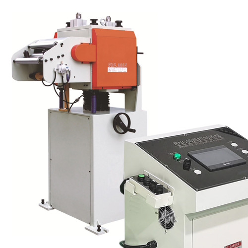
Sizing the drive on an NC servo feeder is a four-input calculation that any engineer can run in ten minutes, and running it changes what you specify. This article works through a real example, shows which input dominates the result, and explains the point at which a larger motor stops buying anything at all. If the machine is still being specified, the NC servo feeder range lists the drive, roll and loop options these numbers map onto.
Four Inputs That Set the Torque
Strip geometry and back tension come from the process. Acceleration and friction come from how the line is run. All four feed the same equation, and leaving any one of them out is how a machine ends up under-sized.
- Strip cross-section. Thickness × width gives the area that back tension acts on. On 2.0 mm × 400 mm that is 800 mm², and it is the multiplier on every tension figure.
- Back tension from the coil. Typically 1 to 3 MPa on the strip in a loop-controlled line, rising to 8 MPa or more if the loop is short or the brake is stiff. This is usually the largest single term.
- Acceleration of the strip mass. Feed length divided by acceleration time sets the acceleration; the mass of strip between the loop and the die sets the force. Short feed times on long, wide strip are what make this term matter.
- Guide and roll friction. Strip drag through entry guides and the roll bearings themselves. Small on a clean line, but it doubles if guides are misaligned or the strip is running dry.
Roll pressure is not on that list because it is not an input to the force calculation — it is the answer to a different question. More on that below.
Working the Numbers for a 2.0 mm Strip
Take a press feeder running 2.0 mm × 400 mm SPCC, feed length 250 mm, 45 strokes a minute, with a loop of roughly 2.5 m of strip between the loop roller and the die. Strip mass is 6.28 kg per metre.
| Term | Basis | Force |
|---|---|---|
| Back tension | 2.0 MPa × 800 mm² of strip section | 1,600 N |
| Strip acceleration | 15.7 kg over 2.5 m, 0 to 0.19 m/s in 60 ms | 105 N |
| Guide and bearing friction | Estimated from guide drag at running tension | 150 N |
| Required pull force | Sum of the above | 1,855 N |
| Grip force at the rolls | 1,855 N ÷ (2 × 0.12 friction coefficient) | 7,730 N |
| Roll shaft torque | 1,855 N × 0.060 m roll radius, +15% for inertia and bearings | 128 N·m |
| Motor torque | 128 N·m ÷ (10:1 gearbox × 0.90 efficiency) | 14.2 N·m |
That 14.2 N·m is the number to specify against, and it is a peak figure rather than a continuous one, because acceleration occupies only part of the stroke cycle. A 1.5 kW servo running at 2,000 rpm gives roughly 7.2 N·m continuous and about 21 N·m at peak, so the duty sits at roughly two thirds of peak capability. That works, but it leaves little room for a heavier coil or a shorter feed time. A 2.0 kW drive puts the same duty at under half of peak and is the more comfortable specification for a line that may later run 2.5 mm material.

Acceleration Is Where Most Sizing Goes Wrong
The acceleration term looks small in the table above — 105 N against 1,600 N of back tension — and on this line it is. Change the feed profile and it stops being small.
Servo feeders are sold on short cycle times, and a short cycle means a short acceleration window. Halving the acceleration time from 60 ms to 30 ms doubles the acceleration force, and the same strip now needs 210 N instead of 105 N. Shorten it to 20 ms and it needs 315 N. On a light, narrow strip that is still a minor term, but on 4.0 mm × 600 mm material the moving mass rises to about 38 kg and the same 20 ms window asks for more than 900 N.
The practical consequence is that a feeder sized on steady-state pull force alone will be marginal on fast jobs and comfortable on slow ones, which is exactly the pattern shops report when a machine "runs fine at 30 SPM and struggles at 70". The fix is not always a bigger motor. Increasing the acceleration time by 10 ms is often enough, and it costs nothing but a few strokes a minute.
One caution on the numbers: the acceleration force is also affected by how much strip is free to move. A line with a short loop, tight guides and a heavy coil brake is accelerating the strip against a stiffer spring than a line with a long, slack loop. Sizing on a long loop underestimates the force a tight line will demand.
Which Input Moves the Answer Most
Run the same calculation with each input varied by 50% and the ranking is clear enough to guide a specification.
Back tension dominates. Going from 2.0 MPa to 3.0 MPa on this strip adds 800 N to the pull force, which is more than the acceleration and friction terms combined. This is why loop control and brake setting matter more to feeder sizing than most buyers expect: a stiff brake effectively resizes the feeder.
Strip thickness matters almost as much, because it multiplies the section area and the moving mass at the same time. Moving from 2.0 mm to 3.0 mm raises the required pull force by roughly half again before any change in speed.
Friction coefficient is the input people forget. Everything above assumes the strip grips the rolls well enough to transfer 1,855 N of pull. The friction coefficient between oily steel and a polyurethane roll surface typically falls between 0.10 and 0.15. Drop it to 0.08 — heavy drawing oil, polished rolls, a cold morning — and the grip force needed to avoid slip rises from 7,730 N to about 11,600 N. That figure may exceed what the roll pressure system can deliver, and no amount of motor torque compensates for it.
Acceleration is the least influential term on a wide, slow line and the most influential one on a narrow, fast line. It is worth calculating rather than assuming in either direction.
Should the feeder be sized on peak or continuous torque?
Size on peak, then check the duty cycle. Acceleration occupies roughly a quarter to a third of a typical feed cycle, so the RMS torque over the cycle is well below the peak. A drive whose continuous rating covers the RMS figure and whose peak rating covers the acceleration figure is correctly sized.
Does roll diameter change the motor size?
Yes, linearly. Torque is force times radius, so a 120 mm roll needs half the shaft torque of a 240 mm roll for the same pull force. Larger rolls are chosen for grip and strip support, and the drive is then sized to match.
How is back tension measured on a running line?
The practical method is a load cell or a tension meter on the strip between the loop and the feeder. Where that is not available, calculate from the brake torque and the coil radius, and treat the result as an upper bound, since the loop absorbs part of it.
What happens if the feeder is oversized?
Less than you might expect. A larger servo with the correct current limits behaves the same as a smaller one at normal load, and the spare capacity covers later changes in material. The real cost is purchase price, not performance.
Checking the Sizing, and the Limit a Bigger Motor Cannot Move
Two acceptance checks turn the calculation into something you can hold a supplier to.
The slip check. At maximum roll pressure, with the strip you actually run and the lubricant you actually use, the feeder must feed a full coil without losing position. Measure it the same way the machine is rated: dial indicator or laser on the strip, 200 consecutive strokes, and note the speed. If position loss appears on a heavy coil but not on a light one, the machine is at its grip limit and the answer is more roll pressure or a different roll surface, not a bigger motor.
The duty check. Ask for the drive's RMS torque at your duty cycle, not just its rated power. A 2.0 kW drive on a machine whose real cycle demands 16 N·m RMS is working harder than a 1.5 kW drive on a machine demanding 8 N·m, and the nameplate will not tell you which is which.
Feeding accuracy of ±0.05 mm is achievable on this class of machine, and the 80+ engineers who design these lines will confirm that the figure depends far more on grip consistency and loop stability than on motor rating. A large drive on slipping rolls produces the same scrap as a small one.
The most useful result of running the calculation is knowing the limit that a bigger drive cannot move.
Once the required grip force approaches what the rolls can generate, additional motor torque is transferred into roll slip. The strip still does not advance, the rolls polish the surface, and the drive current climbs. Shops that respond to feed errors by specifying a larger servo often find the problem unchanged, because the constraint was never torque.
The three levers that actually raise the ceiling are roll surface and pressure, loop stability, and lubricant control. Increasing roll pressure is the most direct and the cheapest, up to the point where the roll surface starts marking the strip or the bearings are overloaded. Extending the loop and softening the brake reduces back tension and lowers the force the rolls must transfer. And keeping the strip lubricated consistently — not flooding it — keeps the friction coefficient in the range the machine was sized for.
Size the motor properly, then check the grip. On a coil line the second number is usually the one that decides what the machine can do.
Specifying a servo feeder for a new press? Send us your strip data, feed length and target strokes per minute, and our engineers will return a sized drive, roll pressure and loop recommendation.