How Much Coil Camber Can a Die Guide Absorb?
One millimetre of camber over two metres sounds like nothing. On a 1,200 mm wide strip it puts one edge half a millimetre longer than the other for every metre fed, and the die guide takes the difference.
Camber is the defect that coil line buyers blame on the machine and find in the slitter. This works through how much a guide can absorb, what it does to pilots, and the point where the coil has to go back.
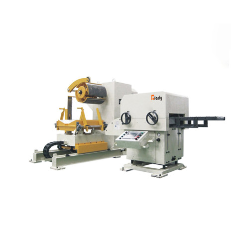
The numbers below come from NC straightener feeder lines running progressive dies on 0.8-3.0 mm stock, where camber shows up fastest.
Measure Camber in Millimetres per Metre
Camber is a lateral bow, measured in the plane of the strip. Lay two metres on the floor and measure the maximum gap between the strip edge and a straight line.
That single number, in millimetres per two metres, is the only one worth quoting. Degrees and percentages hide the scale that matters.
Master coil from a reputable mill typically arrives at 0.5-1.5 mm per 2 m. Coil slit to width by a job shop often arrives at 2-4 mm per 2 m, because slitting adds bow.
Measure at three places: the outer wrap, the middle, and 5 m in. Camber is not constant, and the inner wraps are usually the worst.
Measure with the strip on a flat floor, not hanging over a rack. Gravity adds its own curve and doubles the reading on light gauge.
The same discipline applies to the machine order: state the coil widths you will run, since a wider line absorbs camber better than a narrow one only because the guide has more room.
The Guide Clearance Arithmetic
A die guide is not a straightener. It holds the strip within a clearance, usually 0.1-0.3 mm per side, and it does not bend the strip back.
Camber converts to lateral displacement over the die length. At 1 mm per 2 m, a 1,200 mm long die sees about 0.6 mm of sideways drift between entry and first station.
Compare that 0.6 mm against 0.2 mm of clearance and the conclusion is immediate. The strip reaches the guide face before it reaches the first pilot.
The same camber changes edge length. At 1 mm per 2 m the bow radius is roughly 500 m, so a 1,000 mm wide strip feeds one edge about 1 mm longer per metre.

That edge-length difference is what produces a part that is square at the first station and 0.4 mm off at the last. Operators chase it with guide shims for a week.
| Camber, mm per 2 m | What the die sees on a 1,200 mm die | Where it costs you |
|---|---|---|
| 0.5 | 0.3 mm drift, inside a 0.3 mm guide | Nothing measurable on parts over 5,000 strokes |
| 1.0 | 0.6 mm drift, guide contact at station 1 | Guide face wear, 0.2 mm squareness error |
| 2.0 | 1.2 mm drift, strip rides one guide | Pilot pin scuffing, one-edge burr |
| 3.0 | 1.8 mm drift, guide opened by force | Pilot breakage, die repair inside a month |
| 4.0 and over | Strip steers itself out of the guide | Misfeed, die crash, coil rejection |
What Camber Does to Pilot Pins and the Carrier
Pilots are the part of the tool that pays for camber, and they pay in a way that is easy to misread as a feeder fault.
A pilot entering a hole that has moved 0.5 mm sideways is not locating; it is pushing. The pin takes a side load it was never designed for.
Hardened pilots on 1.5 mm CRS show a bright flat on one side after 40,000-80,000 strokes. That flat is the camber signature.
The carrier rail takes the second hit. As the strip is pushed against one guide, the carrier stretches on that side and the pitch between stations opens by 0.05-0.15 mm.
Operators see the result as a progressive drift in hole position, always in the same direction, always worse at the end of a coil.
Adjusting feed length cannot fix it. Feed length is a machine setting; camber is a geometry error that repeats every stroke.
Separate Camber From Crossbow and Edge Wave
Three defects arrive on the same coil and get blamed on the same machine. They have different causes and different fixes.
Camber is lateral, in the strip plane, and comes from slitting. It does not change when you adjust roll penetration.
Crossbow is transverse, out of plane, and comes from coiling tension. It flattens under roll pressure, which is why it disappears after the straightener and reappears in the part.
Edge wave is a length difference across the width from the rolling mill. It shows as a loose edge and gets worse as the strip is straightened.
The test is simple. Cut a 1 m sample, lay it on a surface plate, and look from the edge. Lateral bow is camber, a hump across the width is crossbow, a wavy edge is edge wave.
Vertical flatness is covered separately in the coil line guide library, because roll geometry does not touch camber at all.
Set the Line for the Camber You Actually Have
Once camber is measured, three adjustments buy time without touching the coil. None of them removes the bow.
Open the guide clearance to 0.4 mm per side and accept 0.2 mm of squareness error. That is a production decision, not an engineering fix.
Run the strip with a slight side pre-load against the fixed guide, so the strip tracks on one face instead of oscillating between two.
Reduce the unsupported span between the straightener exit and the guide entry. Every 100 mm of free strip adds about 0.05 mm of wander at 60 SPM.
- Measure camber per coil and record it against the coil number.
- Set guide clearance from the measurement, not from habit.
- Shorten the free span between the exit rolls and the guide.
- Log squareness at the first and last station every shift.
Every one of those changes is visible in the part, and every one of them costs either tolerance or speed. Write down which one you traded.
When to Send the Coil Back Instead
There is a camber level where line adjustment stops being engineering and becomes denial. Two conditions define it.
The first is repeatability. If two consecutive coils from the same slitter run over 3 mm per 2 m, the problem is upstream and will not average out.
The second is die cost. Once a pilot set has been replaced inside 12 months for side wear, the camber is costing more than the coil is worth.
A slitter can usually correct 1-2 mm per 2 m by adjusting knife clearance and tension. Above that the coil has to be re-slit, and re-slitting loses 8-15 mm of width.
Check the width you will be left with before you ask for re-slitting. A 1,000 mm requirement fed from a 1,010 mm coil has no room for the correction.
Put the acceptance limit in the purchase order as a number with a measurement method. "Straight" is not a specification a supplier can fail.

Where These Numbers Stop Working
The arithmetic above assumes a strip that is flat across its width and reasonably stiff. Three cases break that assumption.
Wide, thin strip is the first. On 1,800 mm by 0.5 mm material the strip buckles before it pushes a guide, so the camber shows as a wrinkle rather than a drift.
Short dies are the second. A 400 mm die sees only 0.2 mm of drift from 1 mm of camber, and the guide absorbs it without any measurable part error.
The third is a coil measured on a rack. Hanging strip reads two to three times its true camber, and buyers have rejected good coils on that reading.
None of this arithmetic says a straightener feeder can correct camber. It cannot, because every roll in the machine works in the vertical plane.
A line that claims to fix camber is describing a side guide with power, which steers the strip and does not straighten it. That is a useful distinction at the quotation stage.
The practical conclusion is unglamorous: measure the coil, set the guide to the measurement, and hold the slitter to a number you wrote down.
How much camber can a die guide absorb on a 1,200 mm die?
About 1 mm per 2 m, with 0.3 mm per side of clearance. Beyond that the strip contacts the guide face before the first pilot engages.
Does camber change the feed length on one edge?
Yes. At 1 mm per 2 m on a 1,000 mm wide strip, one edge feeds roughly 1 mm longer per metre than the other, which shows as squareness drift.
Can a 3-in-1 straightener feeder remove camber?
No. Roll penetration works in the vertical plane. Camber is lateral and has to be corrected at the slitter or accepted at the guide.
What camber limit should a purchase order specify?
1.0 mm per 2 m for dies under 1,000 mm, and 0.5 mm per 2 m for wide progressive dies. State the chord length and the measurement method.
Where to go next
Camber is the lateral half of strip geometry. The vertical half, from roll count to penetration, sits in our coil line knowledge base and explains why the same coil can be flat and still cut crooked parts.
The Coil Line Guide Library