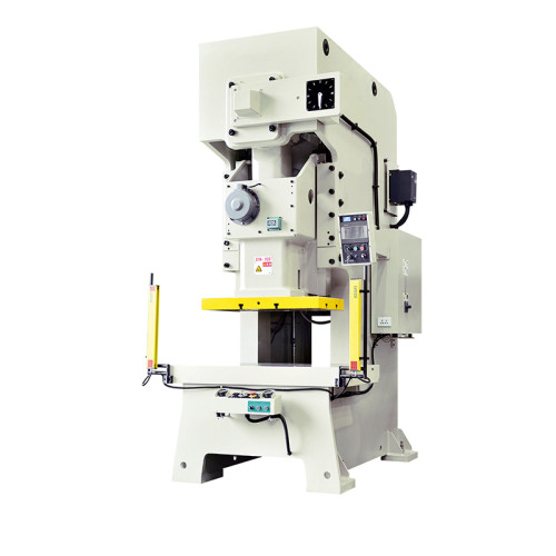
How Much Brake Torque Does an NC Straightener Feeder Need?
The decoiler brake on a coil line is the setting most often copied from the previous job and least often calculated. That works until it does not. Last autumn I stood beside a 1,200 kg coil of 1.2 mm cold-rolled steel running at 240 SPM while the operator explained that the line "always runs a bit loose." The brake was set to a torque figure someone had written on the panel with a marker three years earlier, for a different material and a coil a third the weight. The strip was pulling the loop tight, the straightener was working against varying entry tension, and the flatness gauge had been reading high all week.
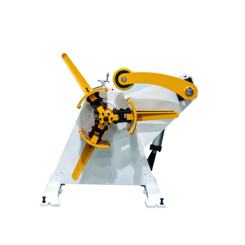
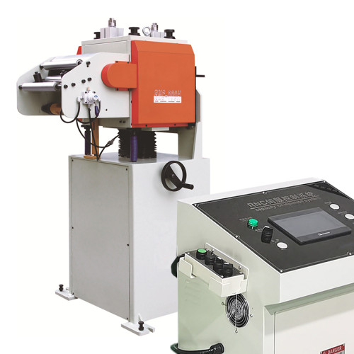
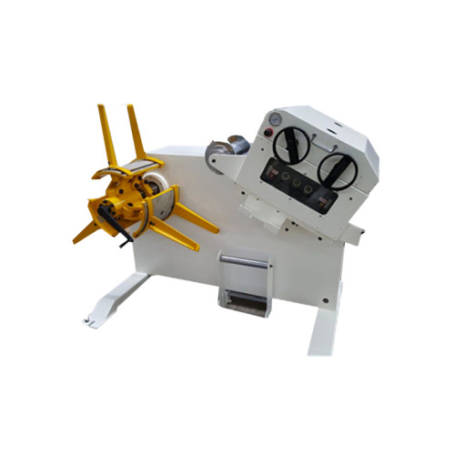
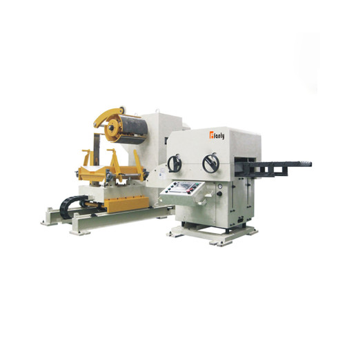
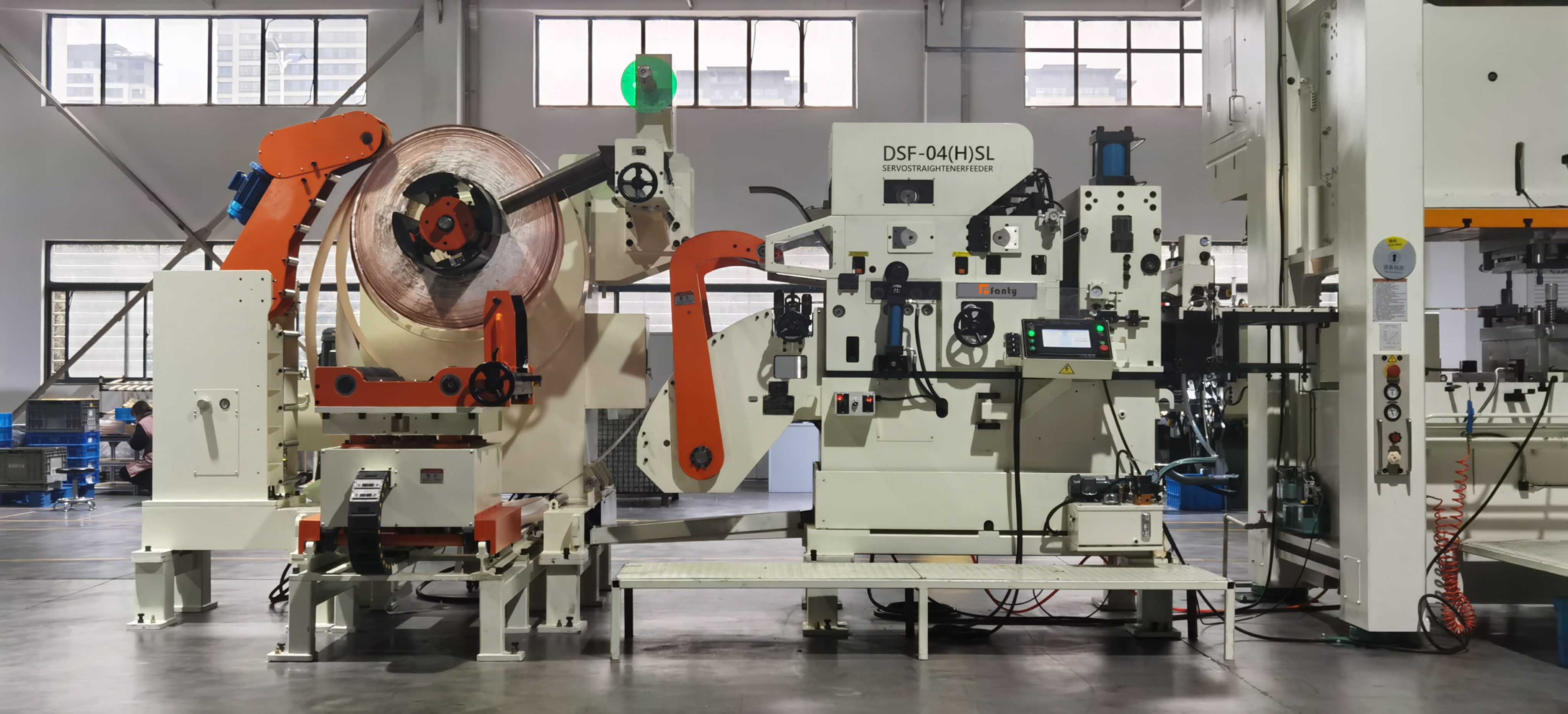
Brake torque on an NC Straightener Feeder is not a preference. It is a number you can calculate from your strip, your coil and your speed, and it should be verified on the machine with a loop measurement. Get it right and the straightener receives strip at consistent tension, which is the only condition under which its own settings mean anything. Get it wrong and every downstream adjustment becomes a guess. If you want to see how the brake section integrates into a full line, our coil feeding equipment range shows the layout.
Size the Brake for the Worst Case, Not the Average
The mistake in almost every brake sizing I have reviewed is that it uses average conditions. Average strip width, average material grade, average coil. A brake sized for average conditions will be wrong on the first coil of the day and wrong again on the last.
What actually sets the requirement is the combination that produces the highest strip tension demand at the largest coil radius. That means maximum strip width, maximum thickness, highest yield strength and a full coil at maximum outer diameter, all at once. In practice the maximum-width and maximum-diameter coils rarely coincide on the same job, so the honest approach is to calculate the torque for each job you run and set the brake to the highest value in the schedule, then verify the low end still gives you enough tension.
There is a second worst case that people forget: minimum width with maximum thickness. A 60 mm wide strip of 3.0 mm material has a small cross-section but very high stiffness, so it transmits tension changes to the straightener with almost no damping. On narrow strip, tension variation shows up as flatness variation rather than as a loop change, which is why narrow-strip jobs are the ones where brake settings get argued about.
Three Loads the Brake Has to Balance
A decoiler brake is not holding a stationary coil. It is controlling three separate loads simultaneously, and only one of them is constant.
The first is strip tension, the steady pull the feeder applies through the strip. This is the dominant load and the one the calculation targets. The second is rotational inertia, the torque needed to accelerate the coil from rest each time the feeder pulls strip. The third is friction in the mandrel bearings and the brake itself, which is small but not zero and changes as the machine warms.
Most operators assume inertia is the big one because a heavy coil feels heavy. The arithmetic says otherwise. On a 1,200 kg coil at 1,400 mm outer diameter, the inertia torque during a typical feed acceleration is roughly one tenth of the steady tension torque. Friction is smaller still. So the sizing question is almost entirely about tension, and the inertia term matters only at very high stroke rates or with very large diameter coils.
| Parameter | Example value | Why it matters |
|---|---|---|
| Strip width × thickness | 300 mm × 1.2 mm | Sets the cross-section the tension acts on |
| Material yield strength | 350 MPa | Tension is normally expressed as a percentage of yield, not an absolute force |
| Target back tension | 4-6 percent of yield | Below 3 percent the strip goes slack; above 8 percent the straightener cannot pull it flat |
| Coil outer diameter | 1,400 mm | Radius multiplies tension into torque |
| Coil weight | 1,200 kg | Drives the inertia term, which is secondary |
| Line speed | 240 SPM at 45 mm pitch | Sets the acceleration available and the inertia torque |
| Calculated steady torque | ≈ 4.4 kN·m at full radius | The number the brake has to hold, and the one to verify on the machine |
Work the example through and you get a cross-section of 360 mm², a yield force of about 126 kN, a tension of 5 percent of that at roughly 6.3 kN, and a torque of 6.3 kN multiplied by the 0.7 m coil radius, which lands near 4.4 kN·m. That figure is the steady holding torque at a full coil. As the coil unwinds and the radius drops, the same tension needs less torque, which is exactly why a fixed brake setting produces a line that runs correctly at the start of a coil and sloppily at the end.
What Over-Braking Actually Does
Too much brake torque feels safe. The loop stays tight, the strip looks controlled, and the operator stops worrying about it. The damage happens where you are not looking.
Over-braking raises entry tension above the range the straightener was set for. The leveler now has to overcome that tension as well as remove the coil set, so the rolls are working against a strip that is already partly stretched. On 1.2 mm material, raising back tension from 5 to 9 percent of yield changes the strip's effective yield by a measurable amount and shifts the required roll intermesh. If nobody re-levels the machine, flatness degrades by roughly 0.3 mm over a 1,000 mm length, which is enough to fail a typical automotive appearance standard.
There is a second, more expensive consequence. Sustained high back tension pulls the coil wrap tight against the mandrel, and on a segmented mandrel that increases radial load on the wedges. Over months, this is what produces the 0.5 mm runout that shows up later as camber. The brake setting and the mandrel's service life are directly connected, and almost nobody treats them that way.
What Under-Braking Actually Does
Insufficient brake torque produces the failure everyone recognises: a slack loop that grows until the strip drags, tangles or trips the loop sensor.
The subtler problem comes before the loop collapses. As the loop grows, strip tension at the straightener falls toward zero, and the straightener's ability to remove coil set falls with it. Coil set is removed by bending the strip past its yield point in alternating directions, and that bending depends on the strip being under enough tension to stay in contact with the rolls. A slack strip can skate across the roll surface instead of being bent, which is why under-braked lines produce flatness that varies across the coil width and drifts through the shift.
Under-braking also shows up as feed length error. With no tension holding the strip back, the feed rolls release a strip that is already relaxed and slightly longer than the programmed pitch. The error is small, maybe 0.05 mm per stroke, but it accumulates in a progressive die and it moves with loop height, so it looks random.
Setting and Verifying the Working Range
Calculating a torque figure gives you a starting point. Verifying it on the machine takes about forty minutes and settles the argument permanently.
- Load a full coil of the widest, thickest material in the schedule and run at production speed, not at jog
- Measure loop height at the sensor across twenty strokes and record the range, not just the average
- Check the mandrel-driven payoff: if the coil is being driven rather than braked, the tension reading is meaningless
- Measure flatness at the straightener exit on the first ten metres and again on the last ten, to expose the radius effect
- Write the verified setting on the job setup sheet together with the coil weight and outer diameter it was set for
- Repeat at the lightest coil in the schedule to confirm the low end of the brake range still holds tension
Note the difference between measuring the average loop height and measuring the range. An average that sits perfectly on the sensor target can still hide a 60 mm swing across the stroke, and that swing is what the straightener feels as tension variation. Record the range.
The Radius Problem Nobody Tunes Out
A fixed brake torque is only correct at one coil radius. Since a coil unwinds from roughly 1,400 mm outer diameter down to the mandrel at 480 mm, the correct torque falls by more than half through a single coil. That is a fact of geometry, not a design flaw.
There are three ways to deal with it. The simplest is to set the brake for the small-radius end and accept a slack loop at the start of the coil, which is what most shops do and why most shops fight loop stability for the first ten minutes of every coil. The second is to use a brake with a load-cell or dancer-controlled feedback loop, which adjusts torque automatically as the radius changes. The third, and the one that costs the least, is to size the loop generously and set the brake to the middle of the coil, so the error is split evenly at both ends and stays inside the sensor's tolerance band throughout.
The middle-of-the-coil compromise is what I recommend to most shops running mixed work. It is not perfect at either end, but it never produces a loop collapse, and it keeps entry tension inside a band the straightener can work with. On a line where the same coil weight is run every day, the feedback brake pays for itself; on a job shop running fourteen different coils a week, the compromise setting is usually the better investment.
We build these lines in a 45,000 m² factory with around 370 people on the floor, which means the brake sizing question reaches my desk often enough that I keep the worked examples on hand. The number that surprises buyers most is not the torque figure. It is how much of their flatness problem disappears when the brake stops being an afterthought.
Brake questions from the shop floor
Can I calculate brake torque without knowing the material yield strength?
You can estimate it from the grade family, but the estimate can be off by 30 percent between mild steel and high-strength low-alloy. Ask your coil supplier for the certified yield value; it is on the mill certificate and costs you nothing to obtain.
Does a heavier coil need more brake torque?
Not for tension. Tension torque depends on strip cross-section and coil radius, not coil mass. Mass affects the inertia term, which on a typical line is about a tenth of the tension torque, so it rarely changes the setting.
Why does the loop get loose at the end of a coil?
Because the radius has shrunk and the same brake torque now produces more tension than the feeder needs, or less depending on the control mode. Either way the fixed setting no longer matches the geometry. Set the brake at mid-coil radius or fit a feedback-controlled brake.
Should the decoiler be motorised rather than braked?
For coils above roughly 1,500 kg, or where the same heavy coil runs continuously, a driven decoiler with tension control holds a tighter band than a friction brake. For mixed work with frequent coil changes, a well-set brake is simpler and easier to maintain.
How do I know if my brake pads are worn enough to matter?
Measure loop height range at the start and end of a shift. If the range widens as the machine warms, pad friction is dropping with temperature and the pads are due. A cold-machine setting that drifts hot is the classic symptom.
Not sure your brake is set right?
Send us your strip width, thickness, material grade and coil outer diameter. We will return the torque figure your decoiler section needs, the tension band the straightener should see, and the loop range to look for on the sensor.
Get your brake torque calculated