How Does an NC Straightener Feeder Affect Power Supply?
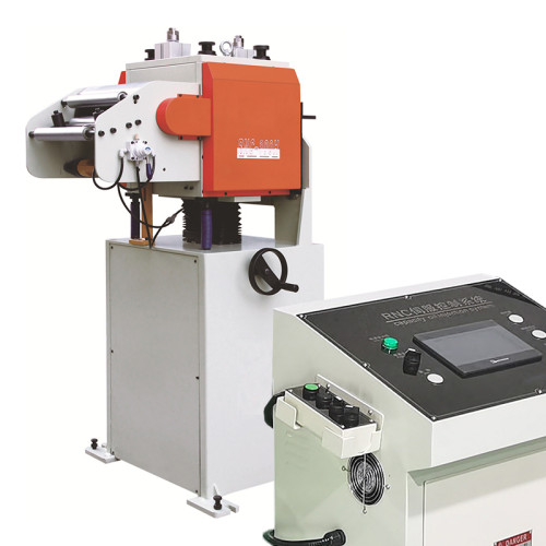
Most coil line buyers spend three weeks comparing straightener roll counts and servo brands, then hand the electrical question to whoever happens to be on site that week. That order is backwards. An NC Straightener Feeder is a servo-driven machine with regenerative drives, an inrush event at every start, and a control cabinet that expects a supply it can trust. Feed it a weak or shared supply and it will still run — it will simply stop holding tolerance the moment the press reaches full stroke. You can review drive ratings across the full NC Straightener Feeder range before you go any further.
This guide covers what a 3-in-1 decoiler straightener feeder really draws, how to size the transformer and feeder cable, why voltage sag turns into a feed accuracy problem, and which numbers to confirm before you sign a purchase order.
What a Coil Line Actually Draws From the Supply
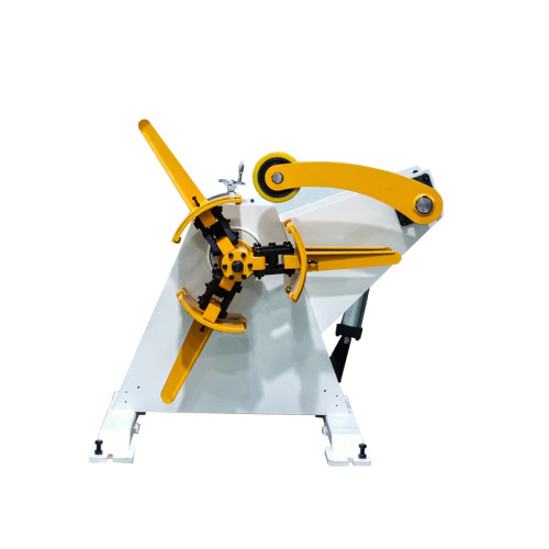
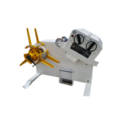
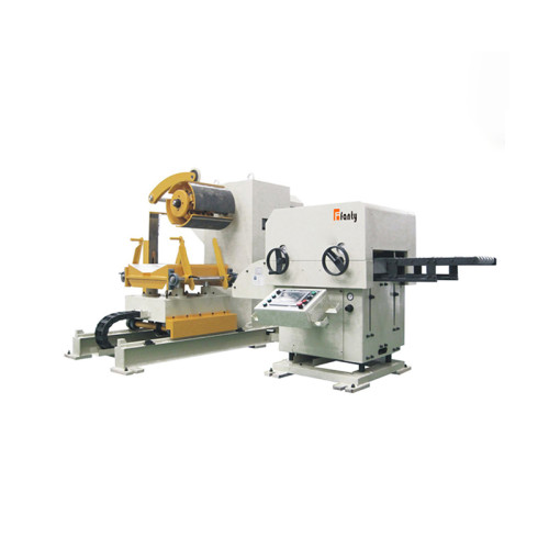
A 3-in-1 decoiler straightener feeder is not one motor. It is four loads sharing a single control cabinet, and they behave differently.
- Straightener drive — runs continuously while strip is moving, so it contributes the steadiest load.
- Feed servo — accelerates and decelerates on every stroke, which makes it the noisiest load on the bus.
- Decoiler motor — intermittent by design, driven by the loop sensor rather than by the press.
- Hydraulic power unit — the expansion pump on the mandrel and any coil car, running in short bursts.
On a typical 800 mm wide, 3.0 mm capacity line, the installed motor total lands somewhere around 18 to 20 kW. That number frightens people who then order a 30 kVA transformer and assume they are safe. They usually are, but not for the reason they think — and on a smaller 400 mm line the same logic fails in the other direction.
Why You Cannot Just Add Up the Nameplates
Nameplate ratings describe mechanical output at the shaft. They say nothing about what the drive pulls from the wall. Three corrections matter.
First, efficiency and power factor. A servo drive converts AC to DC and back again. At the input you see apparent power, measured in kVA, not real power in kW. A 5.5 kW feed motor with 0.87 power factor and 90 percent drive efficiency presents roughly 7 kVA to the supply, not 5.5.
Second, the loads never peak together. The feed servo decelerates while the straightener coasts and the hydraulic unit is idle. A diversity factor of 0.65 to 0.75 is realistic for a 3-in-1 decoiler straightener feeder, and it is the reason a correctly sized transformer is smaller than the sum of the nameplates suggests.
Third, inrush is real but brief. Energising the cabinet pulls 1.8 to 2.5 times rated current for 150 to 250 ms while the DC bus capacitors charge. A standard type C breaker may nuisance-trip on this. Type D, or a drive-rated breaker, handles it without drama.
Run the arithmetic on that 800 mm line and you land near 24 kVA of apparent demand, 17 kW of real demand, and about 31 kVA of transformer if you apply the usual 1.25 multiplier. That is a number you can defend in a site meeting.
Transformer, Cable and Breaker Sizing
The single most common site mistake is hanging the coil line on the same transformer as the press. The press is the dominant load, and every stroke produces a current transient. The feeder sees that transient as a dip on its own bus.

Three rules cover most installations:
- Size the transformer at 1.25 times the calculated apparent demand, then round up to the next standard rating.
- Keep voltage drop across the feeder cable below 3 percent at full load. On a 60 m run at 24 kVA, that usually means 16 mm² copper rather than the 10 mm² a contractor will quote by default.
- Feed the NC servo feeder cabinet from its own breaker. Sharing a breaker with adjacent equipment makes fault-finding a nightmare.
If a dedicated transformer is not possible, a line reactor on the drive input is the cheapest mitigation available. It costs a fraction of a transformer and absorbs most of the commutation notches coming back from the press drives.
Voltage Sag Is an Accuracy Problem, Not a Comfort Problem
Here is the part that surprises experienced buyers. A sagging supply does not usually stop the machine. It quietly degrades position accuracy.
The feed servo holds a commanded position by comparing encoder feedback against a target. When DC bus voltage drops, the drive has less headroom to push current during acceleration. The position loop still closes, but it closes later. On a 250 mm feed at 180 SPM, a 5 percent bus dip typically adds 0.03 to 0.08 mm of positioning error. On a progressive die running 0.5 mm pilot clearance, that is the difference between a clean shift and a scrap bin.
You can measure this in twenty minutes. Log DC bus voltage and commanded versus actual feed position on the same time base. If the position error tracks the voltage dip, the supply is your problem, not the mechanical setup.
Three fixes, in order of cost
- Move the feeder to a stiffer supply point. Free, if the site has one.
- Add a line reactor or isolation transformer. Modest cost, immediate effect.
- Put the control circuit on a small UPS. Keeps the PLC and encoder alive through a press inrush, and prevents nuisance resets.
Site Power Checklist Before You Sign
The table below lists what a supplier should hand you for an 800 mm, 3.0 mm capacity line. If any row is blank on the quotation, ask for it.
| Item | Typical requirement | Why it matters |
|---|---|---|
| Supply | 380–480 V, 3-phase, 50/60 Hz | Confirm before ordering; drives are voltage-specific |
| Installed motor total | 18–20 kW | Baseline for the demand calculation |
| Apparent demand | ~24 kVA | Sets transformer and cable size |
| Recommended transformer | 31 kVA, dedicated if possible | Isolates the line from press transients |
| Feeder cable | 16 mm² copper, <3% drop | Prevents sag on long runs |
| Breaker type | Type D or drive-rated | Tolerates 2× inrush without tripping |
| Earthing | Separate PE, <4 Ω to earth | Required for CE and for drive EMC compliance |
| Ambient | 0–40 °C, <90% RH | Cabinet derating above 40 °C |
FANTY has supplied coil feeding equipment to more than 60 countries, and the power question comes up on every project where the press and the feeder share a building. Getting it settled at quotation stage costs nothing. Getting it settled after commissioning costs a transformer, a shutdown and a new site drawing.
Questions Buyers Ask About Feeder Power
Can I run the coil line from the same panel as the press?
You can, and many plants do. The risk is transient sag during each press stroke, which shows up later as intermittent feed error rather than an obvious fault. If the press is above 100 tonnes, put the NC Straightener Feeder on its own breaker and, ideally, its own transformer winding.
Do I need a generator for a site with unstable mains?
Only if the supply genuinely drops below the drive's minimum input. Size the generator at 1.5 times the apparent demand, not the motor total, because a generator's impedance is much higher than a transformer's and it reacts badly to pulsed servo loads.
What cable size should I prepare before delivery?
Ask the supplier for the drive schedule. For a 24 kVA line at 400 V over 60 m, 16 mm² copper four-core is the safe answer. Undersizing by one step is a common and expensive shortcut.
Does a bigger transformer improve feeding accuracy?
Only up to the point where sag disappears. Beyond that, accuracy is set by roll condition, strip condition and motion profile. A transformer is a fix for an electrical limit, not a general performance upgrade.
How do I confirm the electrical data is correct?
Ask for the drive schedule, the calculated apparent demand and the recommended breaker curve in writing as part of the technical offer. A supplier who cannot produce these has not engineered the electrical side of your line.
Sizing Power for a New Coil Line?
Send us your strip width, thickness range and press speed. Our engineers will return a drive schedule, calculated demand and the electrical data your site drawing needs.
Request the Electrical Data Sheet