Can a Straightener Feeder Fix a Flatness Complaint Alone?
The plant had a flatness complaint on a 300 x 180 mm bracket, a 0.8 mm/m spec, and 12% scrap at the die. They had already decided the line was at fault and booked a service visit to prove it.
It took three visits and one measurement sheet to show that the NC straightener feeder was holding its part of the contract the whole time.
What follows is the sequence as it happened, because the order of the checks is the lesson. The plant measured the wrong thing first, twice.
The Complaint and the Number Behind It
Material was 1.2 mm SPCC, 800 mm wide, from two different mills on rotation. The part was a chassis bracket with two pierced holes and a 90° flange formed in the same stroke.
The flatness call-out was 0.8 mm per metre, measured on a granite table after the part was cut from the strip. Scrap was running at 12%, mostly rocker and twist that showed up at assembly.
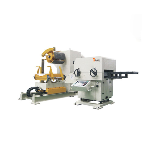
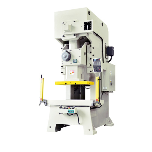
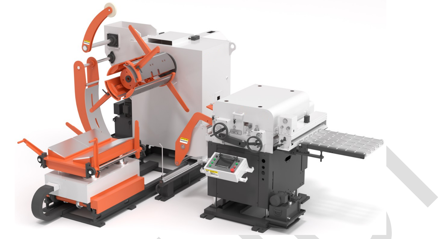
The line was a 3-in-1 unit with a 9-roll straightener, rated 1.2 mm at 800 mm, feeding a 200 t mechanical press at 55 SPM. It had run for fourteen months without a flatness complaint.
What changed was the coil supplier. The plant had switched one of the two mills to a cheaper source three months before the complaint started, and nobody connected the two events.
Visit One: Everything Measured Inside Spec
Roll runout on the nine straightener rolls came in at 0.03-0.05 mm against a 0.08 mm limit. Roll gap was set to 1.15 mm, penetration to 2.5 mm on the bottom set.
Strip flatness straight off the line, measured on a 2 m sample on the plant's own plate, read 0.35-0.5 mm per metre. Inside the 0.8 mm call-out with margin.
The customer's measurement was taken on a 300 mm cut part, not on strip. Those are different measurements, and on this part the difference was 0.4 mm per metre of springback after the flange was formed.
So the line was delivering 0.45 mm and the part was reading 0.85 mm. The gap was created after the straightener, and the first visit ended with a number that pointed downstream.
Visit Two: The Coil Was the Variable
Two coils were pulled from the rack and cut into 1 m samples before they went on the line. One mill's coil had 4 mm per metre of crossbow; the other had 11 mm.
Crossbow is a full-width bow across the strip, and a straightener removes it only within its penetration budget.
At 2.5 mm of penetration on 1.2 mm stock, the machine can take out roughly 8 mm per metre of crossbow and no more.
That explains the pattern without any machine fault. The cheap mill's coil arrived at 11 mm per metre, the straightener removed what it could, and the residual 3 mm went into the die and came out as twist.
The same coil also carried 6 mm per metre of edge wave on one side. Edge wave and crossbow together are the combination that produces rocker in a flanged part, because the two defects add rather than cancel.
| Incoming check | Instrument | Reading that clears the line | Reading that points at the coil |
|---|---|---|---|
| Crossbow across width | Straight edge and feeler | Under 6 mm per metre | Over 9 mm per metre |
| Edge wave | 2 m sample on plate | Under 3 mm per metre | Over 5 mm per metre, one side only |
| Camber | String line on 2 m | Under 2 mm per metre | Over 4 mm per metre, consistent direction |
| Coil set memory | Cut 300 mm, lay flat | Returns flat within 10 min | Stays bowed after 30 min |
None of these checks needs a lab. A straight edge, a feeler gauge, a granite plate and a stopwatch cover all four rows, and the whole set takes 12 minutes per coil.
Visit Three: The Die Absorbed What the Line Left
The residual 3 mm per metre of crossbow does not disappear at the die. It gets clamped, formed and released, and the release is where it turns into twist.
The die's pressure pad was running at 18 t on a 0.6 m² pad, which is low for a flanged part. Raising it to 26 t moved the twist by 0.25 mm per metre on its own.
Pilot clearance was 0.05 mm on a nominal 0.05 mm pin, which sounds correct and was not.
With 3 mm of residual bow, the strip needs 0.08-0.10 mm of clearance or the pilots drag the material into position and pre-load the part.
The third change was the flange sequence. Forming the 90° flange in the same stroke as the pierce meant the part was released from a stressed state, and springback varied with the residual bow in the strip.
Those three changes took the part from 0.85 mm to 0.55 mm per metre. The line settings never moved during any of it.
What the Case Proves and What It Does Not
It proves the line can be inside spec while the part is not. That is the most common shape of a flatness complaint, and it is why the machine gets blamed first.
It does not prove the straightener is innocent in every case. A 9-roll machine with 2.5 mm of penetration on 1.2 mm stock has a real limit, and 11 mm per metre of crossbow is outside it.
Nor does it prove that more rolls would have fixed it. Adding rolls raises the penetration budget by 15-25%, not by 100%, and the coil would still have arrived outside what the machine can absorb.
The measurement method is the part that travels.
Part flatness after forming and strip flatness off the line are different numbers, measured on different samples, and comparing them directly produces the wrong conclusion every time.
One more limit: the case says nothing about speed. Flatness at 55 SPM and flatness at 120 SPM are different, because back tension and loop control behave differently, and the residual bow changes with them.
How to Attribute a Flatness Complaint in Two Hours
Work outward from the strip, not inward from the part. The first sample decides whether the line is even in the argument.
Cut 2 m at production speed, lay it on a plate and measure across the width. If that number is inside the call-out, the line is delivering and the search moves downstream.
Then cut the same coil into 300 mm pieces and let them sit for 30 minutes. A piece that stays bowed is carrying coil set that the straightener could not remove, and no die adjustment fixes it.
Only after both checks does the die get measured. Pad pressure, pilot clearance and forming sequence account for more flatness scrap than most plants expect, and all three are cheaper to change than a roll set.
| Check | What it rules out | Where the reading misleads you |
|---|---|---|
| 2 m strip sample off the line | A line that cannot deliver flatness | Reads clean while the part still twists at the die |
| 300 mm cut, 30 min relaxation | Coil set beyond the penetration budget | Slow recovery looks like an improvement that is not there |
| Die pad pressure at the press | Forming release as the cause | Extra pressure can mask bad strip for a few hundred parts |
| Pilot clearance and pin marks | Drag and pre-load before forming | Reads correct on a flat sample, wrong on a bowed one |
Run the four checks in that order and the answer usually appears at row two. Plants that start at row three spend a week changing die springs.
The cost of getting the order wrong is not the service visit. It is the coil that keeps running because nobody has proved where the bow enters the process, and the scrap that goes with it at 12% for three months.
- Measure strip off the line before measuring parts.
- Sample start, middle and end of the coil; crossbow often grows through the coil.
- Keep the mill certificate with the coil, not in an office file.
- Change one die parameter at a time; pad pressure first.
How much crossbow can a 9-roll straightener remove on 1.2 mm?
Roughly 7-8 mm per metre at 2.5 mm of penetration. Above 9 mm per metre the residual shows up in the part, not on the strip sample.
Why does the part read 0.85 mm when the strip reads 0.45 mm?
Springback after flanging adds 0.3-0.5 mm per metre on a 90° flange. The two numbers measure different things and should never be compared directly.
What pilot clearance suits strip with 3 mm of residual bow?
0.08-0.10 mm on a 0.05 mm nominal pin. Tighter clearance drags the strip and pre-loads the part before forming.
Does more roll pressure fix a flatness complaint?
No. Penetration depth and roll count set the limit; extra pressure above the yield point adds marking and work hardening without removing more bow.
The flatness specification itself is worth re-reading before the next complaint, because most of them start with a number that was written for a different measurement method.
How roll count, pitch, gap and penetration interact to set that limit is covered in the 3-in-1 decoiler straightener feeder guide.
When the residual shows up as curl rather than bow, the cause is usually back tension rather than the roll set, and that is a separate diagnosis. It is worked through in our coil line knowledge base.
Where to go next
This case sits under the flatness cluster: what the machine can absorb, what the coil brings in, and what the die adds. The specification side of that chain is in our knowledge base.
The Coil Line Guide Library